
Low-voltage monitor

The circuit design consists of a voltage divider, a comparator, and an LED indicator. The voltage divider is created using two resistors, which reduce the 12V battery voltage to a lower level suitable for the comparator's input. The values of these resistors can be calculated based on the desired threshold voltage of 10 volts.
The comparator, typically an operational amplifier configured in a non-inverting mode, compares the reduced voltage from the voltage divider with a reference voltage set to correspond to 10 volts. When the battery voltage falls below this threshold, the output of the comparator switches states, signaling that the battery is under-voltage.
The output of the comparator is connected to an LED through a current-limiting resistor. When the comparator output goes high (indicating the battery voltage is below 10 volts), it allows current to flow through the LED, lighting it up and providing a visual warning to the operator.
To enhance the circuit's reliability, a hysteresis feature can be added by incorporating feedback from the comparator output to the non-inverting input. This prevents the LED from flickering when the battery voltage hovers around the threshold level.
Overall, this battery monitoring circuit is a simple yet effective solution for ensuring that automotive batteries do not fall below a critical voltage level, thereby extending battery life and preventing potential vehicle malfunctions.This circuit monitors the voltage of a battery and warns the operator when the battery voltage is below a preset level by tumingon an LED. The values are set for a 12V automobile battery The preset value is 10 volts.
Related Circuits
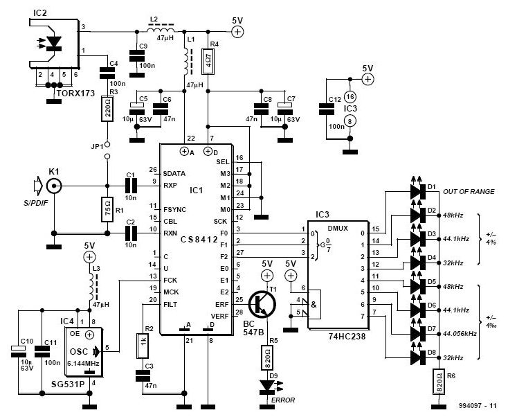
The S/PDIF monitor is an application of the digital audio interface receiver Type CS8412 from Crystal. Previous articles have covered the decoding of S/PDIF (Sony/Philips Digital Interface Format) into data, bit clock, and L/R clock for use in devices...

The circuit principle involves an oxygen sensor circuit utilizing the OS-12, a DC amplifier IC1, an A/D converter IC4, a liquid crystal display F2100-34PI, a voltage comparator IC2, and a positive and negative power converter IC, among other components....
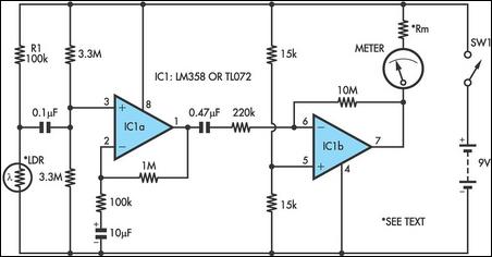
Strictly speaking, this simple circuit should not work. How could anyone expect an ordinary light-dependent resistor (LDR) photo cell to detect changes in blood flow through a fingertip in natural daylight? The secret lies in a high-gain circuit based...

The circuit schematic illustrates a simple audio surveillance system in which the transmitter captures sound from one location, while the receiver reproduces it at another location. Both the transmitter and receiver are connected by a single wire, which carries...
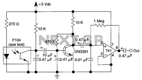
An infrared (IR) photodiode is employed to detect the IR reflectivity of the skin, which changes due to increased blood volume during heart contractions. This device captures a signal that correlates with the heartbeat. A transistor and operational amplifier...
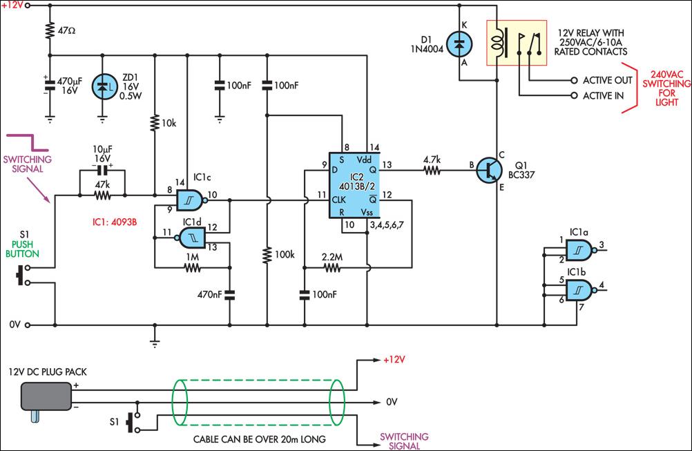
This circuit enables the remote control of a 240V mains appliance, such as a light bulb, through low-voltage cabling and a pushbutton switch. The mains appliance is activated using a suitably-rated relay. All electronic components are housed in an...