
chasing an elusive bug around

The circuit in question involves a DC-DC converter, which is designed to convert a source voltage to a different output voltage level efficiently. The primary components typically include an inductor, a switch (often a transistor), a diode, and a capacitor. The operation of the DC-DC converter can be classified into different types, such as buck, boost, or buck-boost converters, depending on whether the output voltage is lower, higher, or the same as the input voltage.
In debugging the DC-DC converter circuit, it is essential to examine each component's functionality and interactions. The switching element must be functioning correctly to control the energy transfer through the inductor. If the switch is not turning on or off as expected, it can lead to insufficient voltage conversion or excessive ripple on the output.
The diode's role in the circuit is to allow current to flow in one direction while blocking it in the reverse direction, which is critical during the energy transfer phase. If the diode is faulty or incorrectly oriented, it can prevent the circuit from operating as intended.
Capacitance also plays a crucial role in smoothing out the output voltage. Insufficient capacitance may result in high ripple voltage, affecting the performance of the load powered by the converter.
In addition to component verification, the layout of the PCB should be inspected for potential issues such as ground loops, inadequate trace widths, or excessive lengths that could introduce inductance or resistance, leading to performance degradation.
The evidence gathered in this debugging process should lead to a clearer understanding of the issues at hand, allowing for targeted troubleshooting and eventual resolution of the problems in the DC-DC converter circuitry.Since my last post, I have been quite busy debugging my board. There seem to be more than one problems in the implementation of the DC-DC converter circuitry. However, this time I have gathered enough evidence on the bug; whatever it is, it looks that is not the fault of the PIC, nor is the 3210..
🔗 External reference
Related Circuits
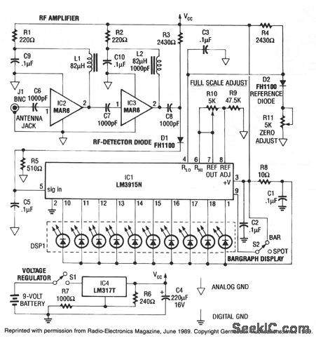
This RF detector can locate low-power transmitters (bugs) that are hidden from sight. It can sense the presence of a 1-mW transmitter at a distance of 20 feet, which is sensitive enough to detect the smallest bug. As the...
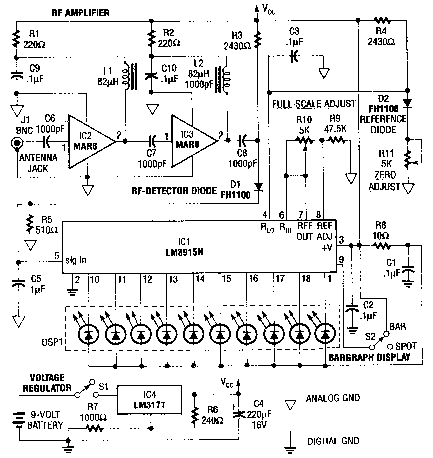
This RF detector is capable of locating low-power transmitters (such as bugs) that are not visible. It can detect the presence of a 1-mW transmitter from a distance of 20 feet, making it sensitive enough to identify even the...
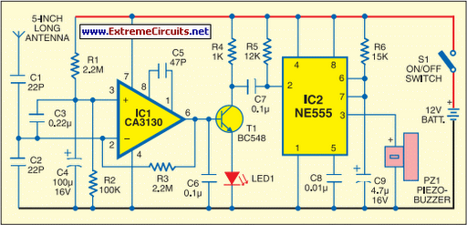
This portable mobile transmission detector can detect the presence of an activated mobile phone from a distance of 1.5 meters. It is designed to prevent the use of mobile phones in examination halls, confidential areas, and other restricted environments....
These two tank circuits appear to broaden the operating spectrum. The accompanying information sheet indicates that when both circuit stages oscillate at the same frequency, the power output reaches its maximum. This suggests that if the tunable tank circuit...
The circuit consists of three stages, an electret microphone, an audio amplifier and an RF oscillator. The electret microphone consists of only two parts - a FET transistor and a plastic diaphragm. There is nothing else inside the case....
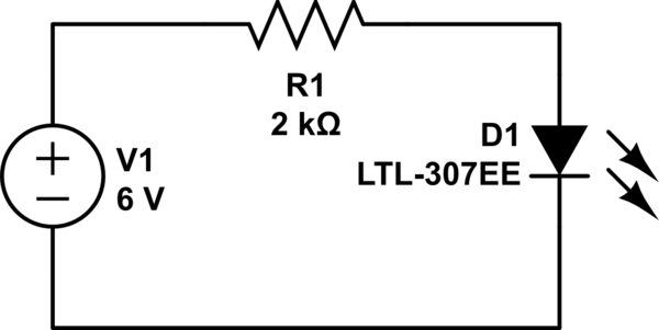
It cannot be 0 volts, as the current does not flow freely due to the presence of the resistor. This results in one side being more negatively charged and the other side more positively charged, as electrons can move...