
led Calculate expected voltage around a resistor

In electrical circuits, the behavior of current flow is significantly impacted by the components present, particularly resistors. When a resistor is introduced into a circuit, it restricts the flow of electrons, leading to a voltage drop across the resistor. This voltage drop is responsible for the difference in charge between the two sides of the circuit.
In a typical scenario, a battery provides a potential difference that drives the current through the circuit. The electrons, which are negatively charged, are attracted towards the positive terminal of the battery. However, as they encounter the resistor, their movement is impeded. This resistance causes a buildup of charge on one side of the resistor, leading to a negative charge accumulation on the side connected to the negative terminal of the battery, while the other side becomes positively charged due to the lack of electrons.
The relationship between voltage (V), current (I), and resistance (R) is described by Ohm's Law, which states that V = I * R. In a circuit with a resistor, the voltage across the resistor can be calculated by multiplying the current flowing through it by its resistance value. This principle helps explain why the voltage cannot be zero; there must always be a potential difference across the resistor as long as current is flowing.
In summary, the presence of a resistor in a circuit creates a scenario where the voltage cannot be zero due to the differential charge distribution caused by the restriction of electron flow. Understanding this fundamental concept is crucial for analyzing and designing electronic circuits effectively.It can`t be 0 volts, since the current does not freely move around, due to the resistor; resulting in one side being more negatively charged, and the other more positively charged, since the electrons can move faster to an end of the battery than through the resistor. 🔗 External reference
Related Circuits
This circuit is a high voltage regulator that features foldback current limiter protection. It utilizes the LM10 comparator along with a voltage reference in its core design. The high voltage regulator circuit is designed to maintain a stable output voltage...
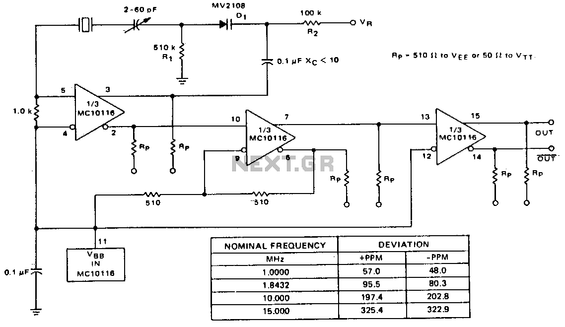
A voltage-variable capacitance tuning diode is connected in series with the crystal feedback path. Adjusting the voltage on the variable resistor (VR) changes the capacitance of the tuning diode, which in turn tunes the oscillator. The 510 kΩ resistor...
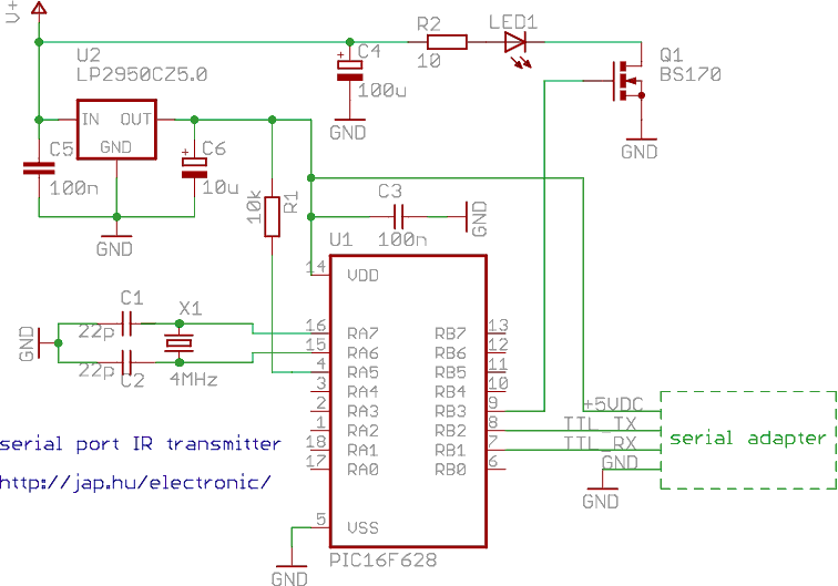
This is a programmable infrared (remote control) transmitter, which can be controlled from a PC serial port. It is capable of sending many remote control formats, including the Philips RC-5 standard. Exact formats with the timing parameter names are...

This circuit is a simple LED voltmeter designed to monitor the charge level of lead-acid or tubular batteries. The terminal voltage of the battery is displayed through four LED indicators. The nominal terminal voltage for a fully charged lead-acid...
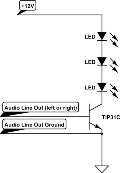
A circuit connects the line output (audio output) of a music-playing device to a large strip of approximately 200 LEDs, allowing them to flash in sync with the music. The circuit functions effectively when using a laptop as the...

This is a flasher circuit that directly derives power from AC to produce brilliant flashes at a rate of one flash per second. It utilizes a DIAC as the main element. The flasher circuit operates by converting alternating current (AC)...