
Cheap AC Current Measurement

The described circuit modification allows for an economical approach to measuring high AC currents using a standard DMM by leveraging a clamp meter's capabilities. The integration of low voltage drop diodes ensures minimal signal loss, which is critical for maintaining measurement accuracy across the specified current range. The choice of power germanium transistors is significant; these components are favored for their low forward voltage drop characteristics, which enhances the circuit's overall performance. The calibration process is essential, as it aligns the output voltage with the multimeter's readings, ensuring that the user can accurately interpret the current measurements. The use of a specific number of turns in the calibration phase is a crucial detail, as it directly influences the scaling of the output voltage to the actual current flowing through the circuit. This method not only provides a cost-effective solution but also enhances the versatility of existing DMMs, allowing them to measure higher currents without the need for expensive equipment.The easy way to measure high AC currents is to use a clamp meter but these are generally quite expensive and cost several hundred dollars at a minimum. Add-on clampmeter adaptors can work well but they only work with digital multimeters which have millivolt AC resolution.
This is because the output of most clamp adaptors is quite low, 0. 1A = 1mV, for example. This is no good for typical cheap DMMs which have a lowest AC voltage range of 200V. This circuit can be built into a low cost clamp meter such as the Digitech QM-1565 from Jaycar Electronics. When dismantling this clamp adaptor, remove the label which has the AC range conversion factors and then undo the two screws gain access to the inside.
The two cross-connected transistors act like low voltage drop diodes to generate a DC voltage which is proportional to the current in the primary of clamp adaptor (ie, the circuit under test). The recommended transistors are power germanium types such as ADZ16, AD162, AD149, ADY16, 2SD471, OC16 and OC28.
This approach gives lowest voltage drop and good linearity, from 10 to 300A. Schottky power diodes can also be used but the result will not be as linear. To calibrate, wind 10 turns through the clamp adaptor`s jaws and feed a current of 20A through the winding. This is equivalent to a single turn carrying 200A. Set the trimpot to suit your multimeter, normally set to the 2V DC range. Do not calibrate for a low current otherwise accuracy at high currents will be poor. 🔗 External reference
Related Circuits
This is an inexpensive DC voltage doubler circuit diagram that requires a minimal number of components and is capable of delivering 10V from a 5V power supply. If the oscillator needs to be... The circuit operates on the principle of...
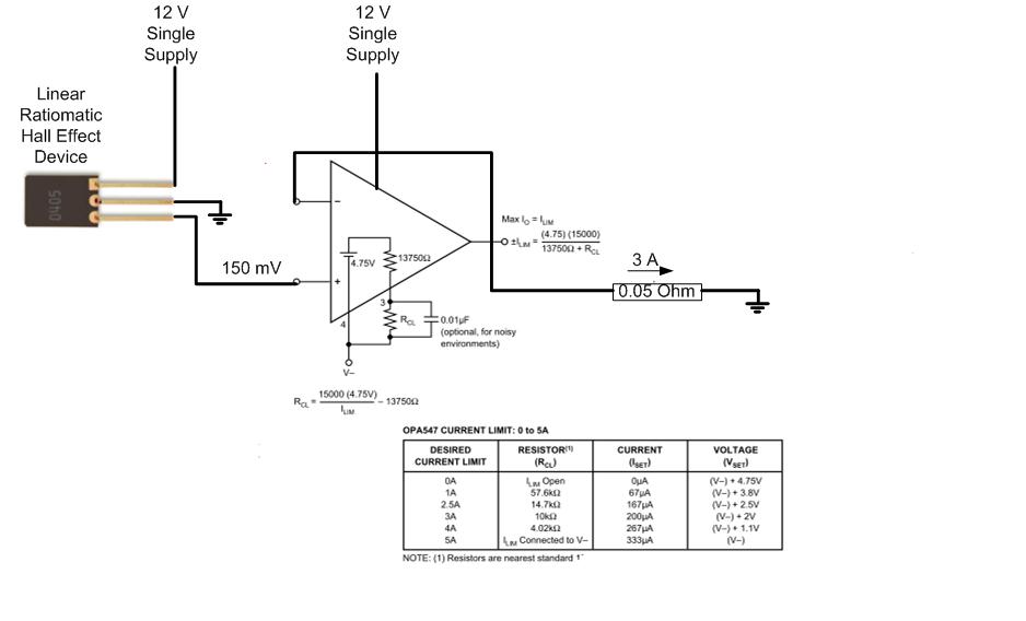
The proposed approach would dissipate (12V)(3A) = 36 watts, which results in significant heat generation in the circuit. This necessitates consideration of two alternatives: 1) Operating the op-amp at a lower supply voltage, if feasible, or 2) Utilizing a...
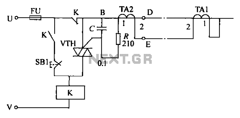
The circuit's current exceeds the load carried by the rated current meter, prompting the user to immediately cut off the power supply to address the overload. Pressing the reset button restores power, making the system simple, convenient, and practical....
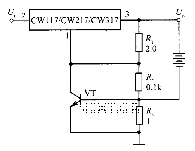
The circuit depicted in the figure is a limiting protection charger. The VT transistors and resistor R3 create a limiting network. As illustrated, resistor R3 is connected in series with the battery being charged, acting as the emitter resistor...
The current source in the diagram reacts very quickly to changes in the input signal and may be utilized in specific measurements. The differential amplifier IC1 ensures that the voltage across resistor R2 is equal to the input voltage,...
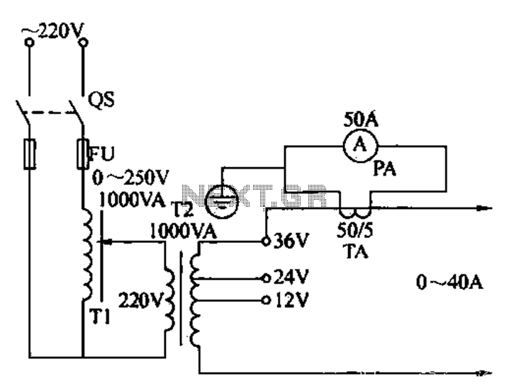
Electricians sometimes use overcurrent relays, thermal relays, and other devices to perform periodic overcurrent checks with a current generator. A secure running lights transformer, voltage regulator, and meter can be constructed using a small electric current generator. The homemade...