
Small current generator circuit

The described circuit serves as a practical solution for electricians needing to conduct regular overcurrent checks. At its core, the circuit includes essential components such as switches for controlling the flow of current, fuse wire for protection against overcurrent conditions, and a regulator to maintain a stable output voltage. The safety running lights transformer is integral to stepping down the voltage to a usable level while ensuring the circuit operates safely.
The current generator operates by converting electrical energy into a controlled output that can be manipulated for testing purposes. The voltage regulator plays a crucial role in this setup, allowing for precise adjustments to the output current. This feature is particularly beneficial for testing various electrical devices and systems under different load conditions.
The ammeter included in the circuit provides real-time feedback on the current flowing through the system, enabling electricians to monitor performance and ensure that the current remains within acceptable limits during testing. The adjustable range from 0 to 40 mA is suitable for a variety of applications, making this circuit versatile for different overcurrent testing scenarios.
In summary, the described homemade ship current generator circuit is a valuable tool for electricians, combining essential components to enable effective overcurrent checks. Its design emphasizes safety and functionality, ensuring reliable performance in a range of electrical testing applications.Electrician sometimes overcurrent relays, thermal relays, etc. do periodic overcurrent or check, to use a current generator. Using secure running lights transformer, voltage re gulator and meter can be made by a small electric current generator. FIG homemade ship current generator circuit, which consists of switches, fuse wire, regulator and safety running lights transformers, ammeter, etc., according to the figure the line is connected, the power supply voltage fed zzov regulator after, the transfer pressure, running lights becomes secondary current voltage regulator can be adjusted from about O 40MA, and continuously adjustable, use it to meet the general overcurrent check.
Related Circuits
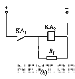
The circuit depicted in Figure 6-24 includes a relay coil with both ends connected in parallel to either a resistor Rf or an auxiliary diode VD. This configuration is equivalent to providing power after a short circuit, which increases...
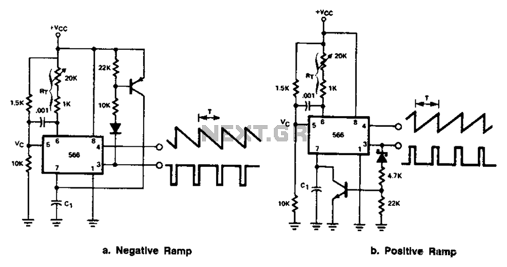
The 566 can be connected to either a positive or negative ramp generator. For a positive ramp generator, an external transistor is driven by the output pin 3. At the end of charging, C1 discharges quickly, allowing for immediate...
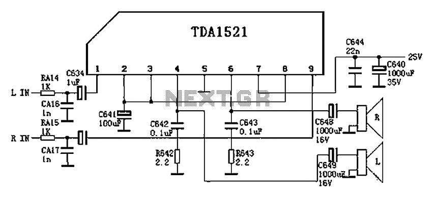
Color is often used in audio circuits like the TDA1521, which is derived from the Changhong C2191 model featuring an OTL two-channel connection. The pin functions and reference voltages for the TDA1521 are as follows: Pin 1: 11V -...
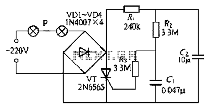
A simple and easy-to-implement one-way flashing lights string controller is designed for small shop or home decoration. This device utilizes a thyristor-based dimmer circuit, which operates effectively by managing large capacitance. The circuit includes a ten-microfarad capacitor connected to...

This is a low-cost FM antenna booster designed to enhance reception of programs from distant FM stations. The FM antenna booster circuit features a common-emitter tuned RF preamplifier utilizing the VHF/UHF transistor 2SC2570 (C2570). The schematic illustrates the configuration...
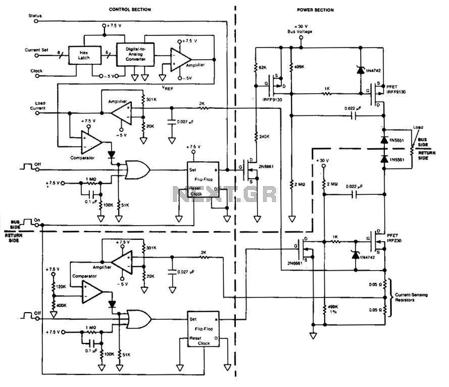
This circuit facilitates on/off switching, soft starting, current monitoring, current tripping, and overcurrent protection for a 30 Vdc power supply, accommodating normal load currents of up to 2 A. The switch is activated by an "on" command pulse and...