
Cheap positive and negative circuit

The circuit operates by utilizing a switch (S1) that plays a crucial role in controlling the flow of current within the system. When the current reaches a predetermined threshold, S1 engages the shut-off switch, effectively interrupting the circuit and halting further current flow. This mechanism is essential for preventing potential damage to components by avoiding overcurrent situations.
In a typical application, S1 can be integrated into various electronic devices to ensure safety and reliability. The design may include additional components such as resistors, capacitors, or diodes to enhance performance and protect against voltage spikes or surges. The shut-off switch can be designed to operate either automatically or manually, depending on the requirements of the specific application.
The configuration of the circuit should be carefully considered, taking into account the expected current ratings and the characteristics of the components used. Proper selection of materials and components will ensure that the circuit functions effectively and safely under various operating conditions. Circuit Description: S1 promote the release of the current reaches the shut-off switch.
Related Circuits
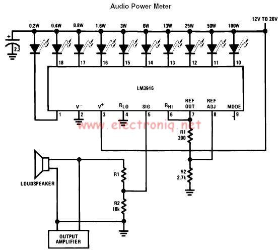
The LM3915 monolithic integrated circuit can be used to design a simple audio power level meter that senses analog voltage levels and drives ten LEDs, LCDs, or vacuum fluorescent displays, providing a logarithmic 3 dB/step analog display. One pin...
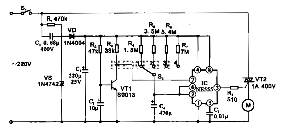
The fan motor driving circuit is depicted as a basic configuration comprising a power circuit and a motor drive circuit. The power supply circuit primarily consists of a power switch (SI), a capacitor (C1), resistors (R1), a Zener diode...
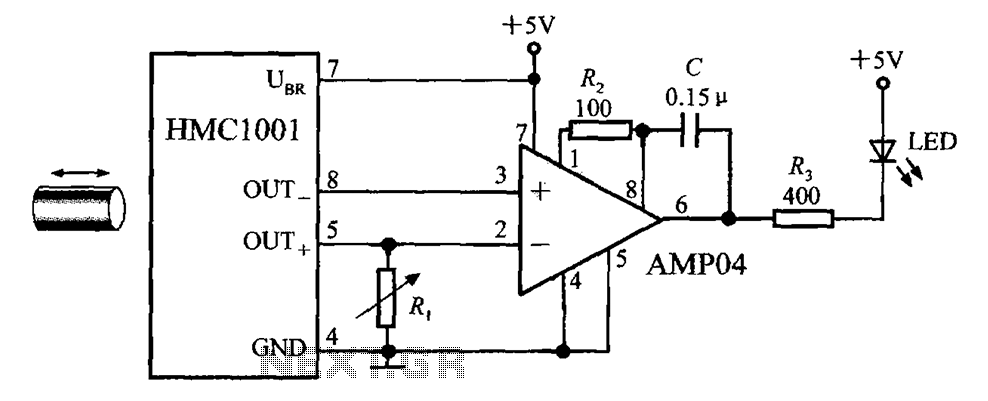
The circuit depicted in the figure includes the HMC1001 magnetic sensor, an operational amplifier (AMP04), and a light-emitting diode (LED), forming a proximity switch circuit. In this application, the operational amplifier functions as a comparator. When a magnet, approximately...
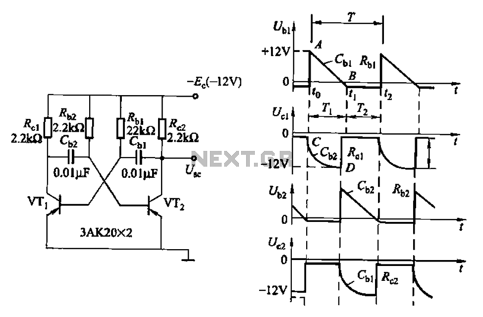
Also known as a no-shot multivibrator, this circuit is often utilized as a pulse (square wave) signal source. The astable flip-flop functions as a strong positive feedback amplifier, with its two branches coupled by an RC timing circuit, resulting...
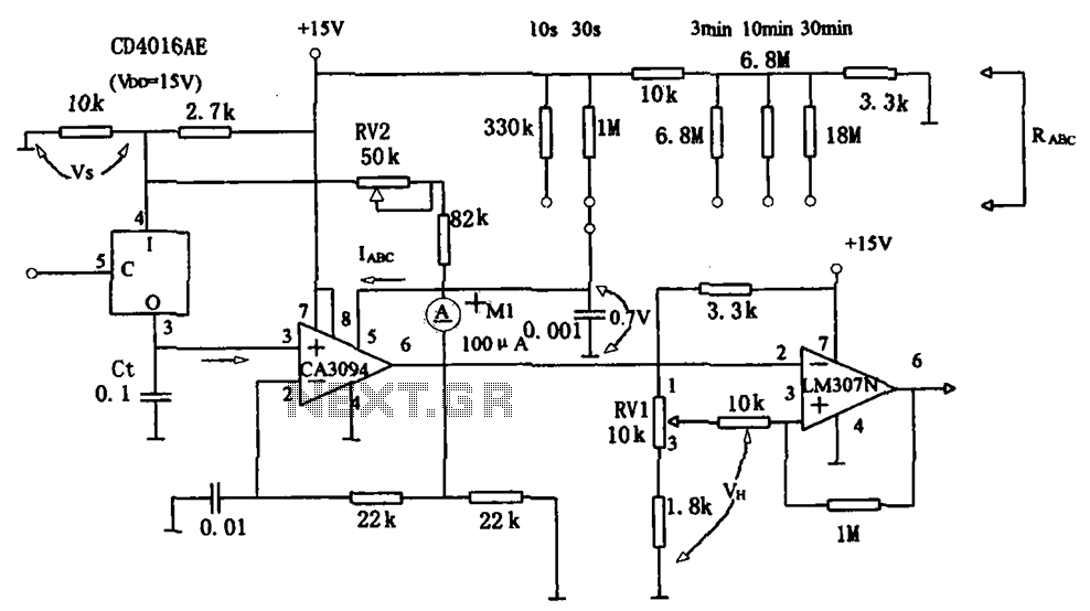
The long timer circuit utilizes an operational amplifier, specifically the CA3094, to control the discharge formula for extended timing. This is typically achieved by adjusting the variable resistor RV1, which alters the timing duration to meet specific requirements. The long...
The basic two-transistor flasher has become widely utilized in various applications due to its simplicity and versatility. It has been employed in circuits such as a micropower low battery indicator, a lightning detector, an off-line switching power supply, a...