
Long timed circuit diagram LM307N CA3094

The long timer circuit is designed to provide extended timing intervals through the use of the CA3094 operational amplifier. The operational amplifier is configured in a manner that allows it to control the discharge of a timing capacitor, creating a delay in the output signal. The timing duration can be modified by adjusting the variable resistor RV1, which changes the resistance in the timing circuit. This adjustment directly influences the charging and discharging rates of the capacitor, thus allowing for precise control over the timing intervals.
In practical applications, the circuit can be employed in various timing applications such as delay timers, pulse generators, or in scenarios where a prolonged timing signal is required. The CA3094 is selected for its favorable characteristics, including low input bias current and high slew rate, which contribute to the overall performance of the timer circuit.
The circuit may also include additional components such as diodes for protection against reverse polarity, capacitors to stabilize the operational amplifier, and resistors to set the gain and timing characteristics. Careful selection of these components, along with the configuration of the operational amplifier, ensures that the circuit operates efficiently and reliably over extended periods.
Overall, this long timer circuit serves as a versatile solution for applications requiring adjustable timing intervals, making it a valuable addition to various electronic systems. As shown for the long timer circuit. This circuit uses an operational amplifier CA3094 controlled discharge formula for long timed, usually by changing the RV1 VH, continuously changing the timing to achieve the purpose.
Related Circuits
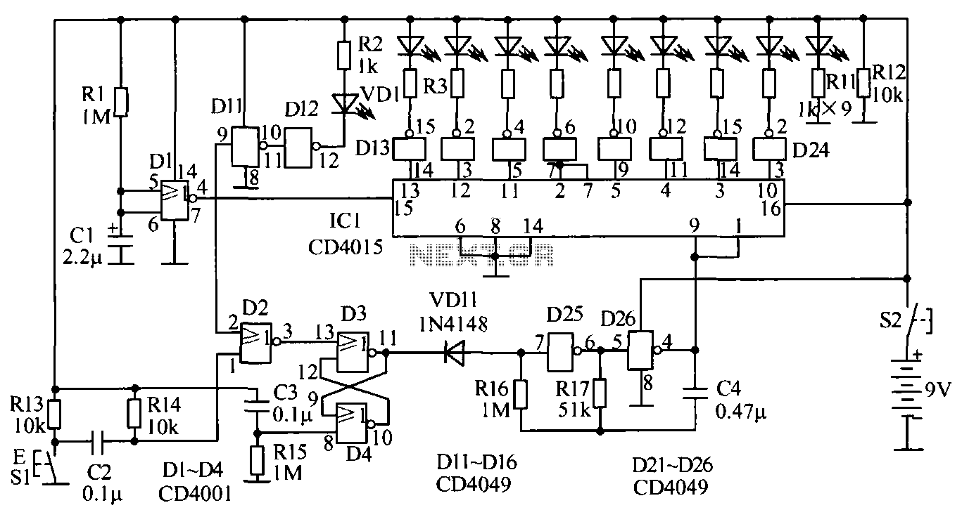
The circuit for testing human reaction speed is illustrated in the figure. It includes NAND gates D25 and D26, along with other components that generate a multivibrator output clock pulse with a period of approximately 50 milliseconds. The circuit...
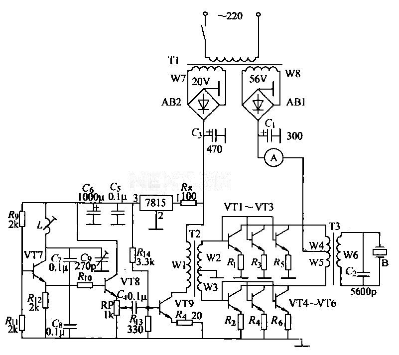
The ultrasonic drilling machine is essential machinery in the dairy industry for processing jewelry, primarily for natural stones, crystal agate, jade, and glass products. This machine is particularly effective for high-hardness materials, enabling both drilling and engraving. The following...
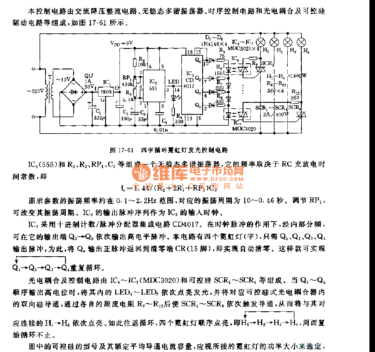
This control circuit consists of an AC step-down rectifier circuit, an astable multivibrator, a timing control circuit, an optocoupler circuit, and an SCR driving circuit, as illustrated in Figure 17-61. The astable multivibrator is formed using IC2 (555), resistors...
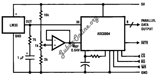
This is a design for a temperature-to-digital converter circuit that is controlled by the LM35 integrated circuit. The LM35 is a precision integrated circuit temperature sensor, whose output voltage is linearly proportional to the Celsius temperature. The circuit utilizes the...
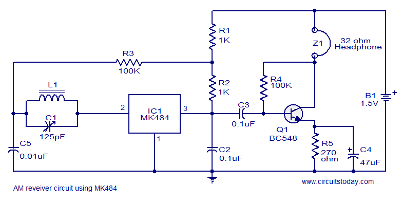
A cost-effective and straightforward AM receiver circuit utilizing the MK484 integrated circuit. The circuit requires minimal external components and operates within a frequency range of 150 kHz to 3 MHz. The MK484 AM receiver circuit is designed for simplicity and...
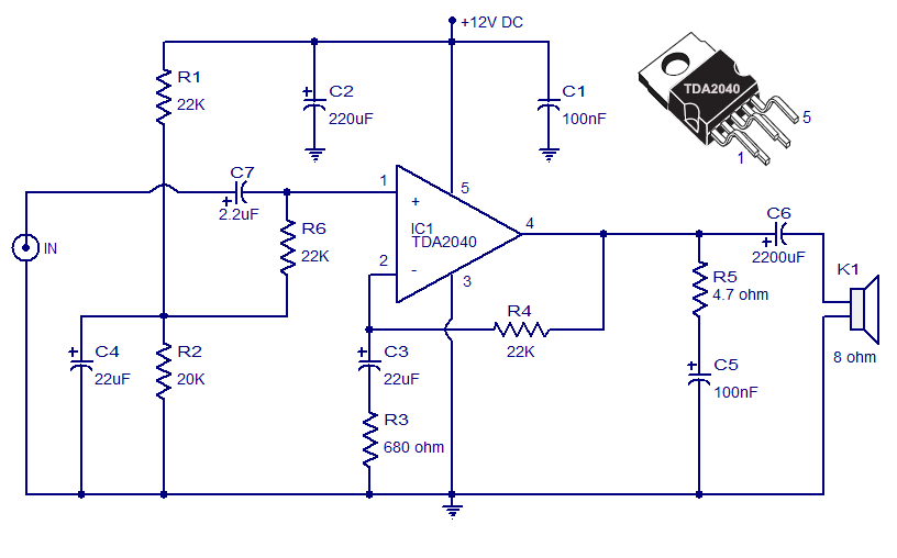
The Car Stereo Amplifier Circuit featuring the TDA2040 is presented here. The TDA2040 is a monolithic integrated audio amplifier that operates in Class AB mode. This integrated circuit includes built-in short circuit protection and thermal management features, allowing it...