
RC coupled self-excited multivibrator circuit

The astable multivibrator is a fundamental electronic circuit that generates a continuous square wave output without requiring any external triggering. It consists of two active devices, typically bipolar junction transistors (BJTs) or operational amplifiers, configured to provide positive feedback. The circuit is characterized by its two timing resistors and capacitors, which determine the frequency and duty cycle of the output waveform.
In a typical astable multivibrator configuration, the two timing components (R1, R2, and C1) are connected in such a way that they charge and discharge alternately, creating a rapid oscillation. The charging and discharging times are governed by the time constants of the RC network, which can be calculated using the formulas:
- Frequency (f) = 1 / (T1 + T2)
- Where T1 = 0.693 * (R1 + R2) * C1 (time high)
- And T2 = 0.693 * R2 * C1 (time low)
This results in a square wave output that can be used in various applications, such as clock pulses for digital circuits, tone generation, and signal modulation. The duty cycle, which is the ratio of the high time to the total period of the waveform, can be adjusted by varying the resistances and capacitance values.
The astable multivibrator is widely used due to its simplicity, low cost, and versatility. It can be implemented using discrete components or integrated circuits, making it suitable for a range of applications in digital electronics, audio signal generation, and timer circuits. Proper design considerations, such as component tolerances and power supply variations, should be taken into account to ensure reliable operation in practical scenarios.Also known as no-shot multivibrator - often used as a pulse (square wave) signal sources. Astable flip-flop is a strong positive feedback amplifier, its two branches are couple d RC timing circuit, so there is no steady state. RC coupled self-excited multivibrator circuit
Related Circuits
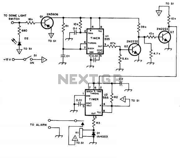
When this car alarm circuit is activated, it remains active for 80 seconds. There is a 15-second delay for the driver to enter and deactivate the alarm. All timings can be easily modified. The circuit utilizes two NE555 timers,...
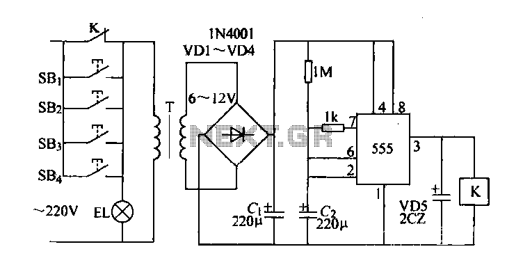
Control buttons SB1 to SB4 can be installed in various positions within a corridor. By pressing any one of these buttons, the EL horse lights will turn on. After releasing the button, the transformer and rectifier supply power to...
This automatic light dimmer circuit enables the gradual control of a lighting system, allowing it to turn on or off slowly. The operation of the circuit is as follows: when switch S1 is closed, capacitor C1 charges slowly. Once...
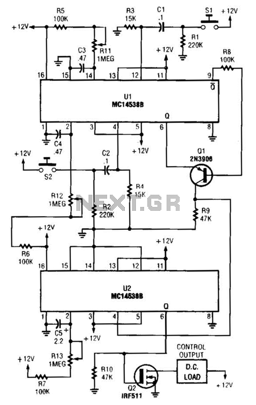
When switch SI is closed, pin 9 of operational amplifier U1 goes low, activating transistor Q1 for a predetermined duration. If switch S2 is closed during this time, transistor Q2 is activated for another predetermined duration. Resistors R1 and...
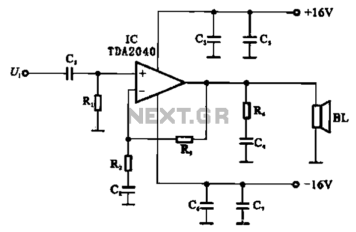
An integrated power amplifier, TDA2040 (IC), can be configured as an OCL (Output Capacitor-Less) power amplifier. The circuit, illustrated in Figure 10-10, operates using a symmetrical ±1V dual supply voltage. The OCL amplifier benefits from the positive and negative...
This infrared transmitter utilizes pulse width modulation (PWM). The transmitter is equipped with an LM567 tone decoder circuit. An audio signal (at least 50 mV peak-to-peak) is amplified with transistor T1 and subsequently used to modulate IC1. The frequency...