
Simple Circuit 12V to 120V DC DC Converter

The circuit operates by first generating a square wave signal at 100 Hz using the NE555 timer IC, which is a versatile component widely used in timer, delay, pulse generation, and oscillator applications. The frequency of the astable multivibrator can be fine-tuned by adjusting the resistor R1, allowing for flexibility in the output frequency.
The dual D flip-flop IC2 is utilized to create two complementary outputs that are 180 degrees out of phase, effectively driving the transformer T1 alternately. This alternating current (AC) generation is crucial for stepping up the voltage through the transformer. The transformer is selected based on its ability to handle the power requirements and the desired transformation ratio to achieve the 120V AC output.
The bridge rectifier D1 converts the induced AC voltage from the transformer into a pulsating DC voltage. The output capacitors C2, C3, and C4 smooth the rectified voltage, reducing ripple and providing a stable DC output. The choice of capacitor values is critical to ensure that the output voltage remains within acceptable limits under varying load conditions.
This circuit is particularly useful in applications where a higher DC voltage is required from a lower voltage source, such as in battery-powered devices or low-voltage power supplies needing higher voltage for specific components or systems. Proper attention to component ratings and thermal management is essential to ensure reliable operation and longevity of the circuit.Its a simple circuit of 12V DC to 120V DC converter. The circuit consists of two phases first phase of the investor base and then a rectifier and filter stage. IC1 NE555 is wired as an astable multivibrator operating at a frequency of 100 Hz and can be adjusted to the preset R1.
IC1 output is coupled to the clock input of IC2 is a dual CMOS D fli p-flop. IC2 divides the pulse train of 100 Hz IC1 2 50 Hz pulse trains that are 180 degrees out of the party and offered on the pin 1 and 2 of IC2. When pin 1 is high transistor Q1 conducts and current flows through the upper half of T1 primary winding.
When pin 2 is the transistor Q2 conducts and high current flows through the lower half of the primary coil T1. As a result of a voltage of 120 V AC are induced in the secondary of T1. This voltage is rectified with bridge D1 to provide a 120V DC output. Capacitor C2 is the DC input filter, while C3, C4 are the output filters. 🔗 External reference
Related Circuits
All of the components in this list are generally available through RadioShack for less than $20. It is highly recommended to use a breadboard for assembly, as mistakes are common for first-time builders, and soldering can complicate troubleshooting. This...

Alarm system designs often require circuitry that can detect whether a phone line is active or broken. The primary challenge in this design is to draw less than 5 µA from the phone line, which operates within a voltage...
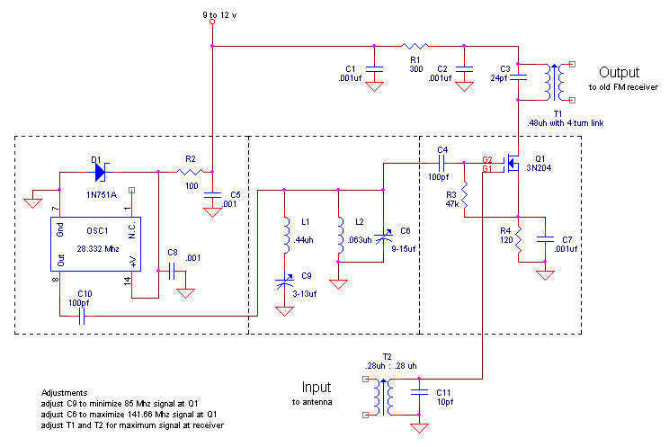
Here is my design for a modern receiving converter for pre-war FM sets. Accordingly, this article presents a design for listening to present day FM stations on a prewar FM set based on a MOSFET transistor and a TTL...
The DTMF infrared remote control circuit utilizes a DTMF encoded signal that can be decoded by a specialized decoder and the PLL audio decoder LM567. However, a DTMF encoded signal decoded by a single decoder yields only one frequency....

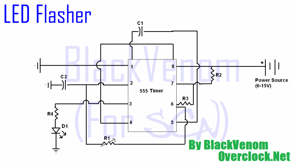
The 555 timer integrated circuit (IC) is an exceptionally versatile component utilized in various applications, including generating clock pulses, switch debouncing, and functioning as an output transducer. The standard 555 IC is packaged in an 8-pin configuration, available in...
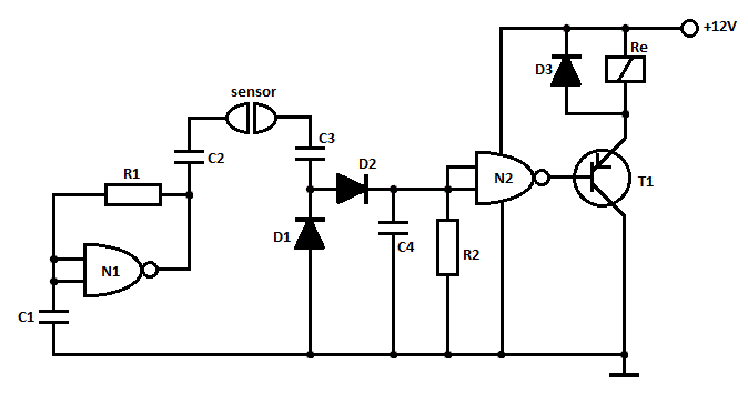
This is a straightforward liquid detector that utilizes a relay to activate an evacuation mechanism. It can be employed for water or any liquid that conducts electricity. Any PNP transistor capable of handling the relay current can be used....