
Single multi-lamp switch control circuit 2

The circuit described operates as a sophisticated lighting control system that can selectively illuminate multiple lamps based on the state of a control switch. This design is particularly advantageous for applications such as chandelier lighting, where different lighting scenarios may be desired. The inclusion of a capacitive buck converter allows for efficient energy management, ensuring that the system can operate effectively even during brief interruptions in power.
The half-wave rectifier (D1) provides a steady voltage to the circuit, while the storage capacitor (C1) ensures that the system can maintain functionality during transient states. The isolation diode (VD2) is crucial in preventing backflow of current, thus protecting sensitive components from potential damage.
The dual D flip-flop (D4) serves as a counting mechanism that tracks the number of switch activations. The timing and sequence of the output states (Q1 and Q2) are configured to control the triacs (VTH1 and VTH2), which in turn manage the power supplied to each lamp. The design allows for flexible control, enabling users to create various ambiance settings by simply toggling the control switch.
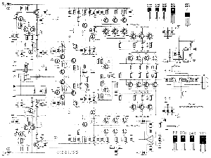
In summary, this circuit design not only provides basic lighting control but also incorporates advanced features that enhance user experience and reliability, making it suitable for modern residential applications.Fig. 296 can use a control switch S El, E2 and E3 three lamp light off. E is suitable for the living room chandelier control. When s off, lights all the fire; for the first tim e together on s, only E1 lit; disconnect S, short-term can be combined within LS, El and E2 lighted; A second break Ji fork turtle Xinhe LS, F1 and F3 point bright; again split off together f S. El-E3 light up. R., Composed of simple capacitive Buck G, v D1, vs the half-wave rectified voltage regulator, etc. c1 line. (For energy storage capacitor when s off fighting f, in time to make marital UM013 UPS can reliably count .VD2 trigger the isolation diode, so (j charge small forward grading electricity.
(, D4 013 is dual D flip-flop, which constitutes a counter device, since R, (1, charge and discharge time constant is small, S each station Ke I split off a second, R: that upper outputs a positive pulse count cI1 feet away! end count that Ql and Q2 ended output high power level by: OO bl0 01 11 00 -- timing variations when Ql, Q2 are output low, that is, 00., only lit E1, E2 and E3 small light; when the output 1 0 ef, thyristor VTH1 opened, so El, E2 lighted when the output 01, VTH2 opened, F1 and E3 lit; when the output ll when, VTHL and VTH2 are Ji Tong, lizard set of lights all light.
playing collapse CI3H-4 () OV polypropylene IU container .VTH1, VTH2 mouth J-type collapse MAC94A4 small plastic triac. other component parameters Figure, no special requirements.
Related Circuits
The following circuit illustrates a 2000W Power Amplifier Circuit Diagram. This circuit utilizes the BC560C transistor. Features include a robust design. The 2000W power amplifier circuit is designed to deliver high output power suitable for various applications, including audio amplification...
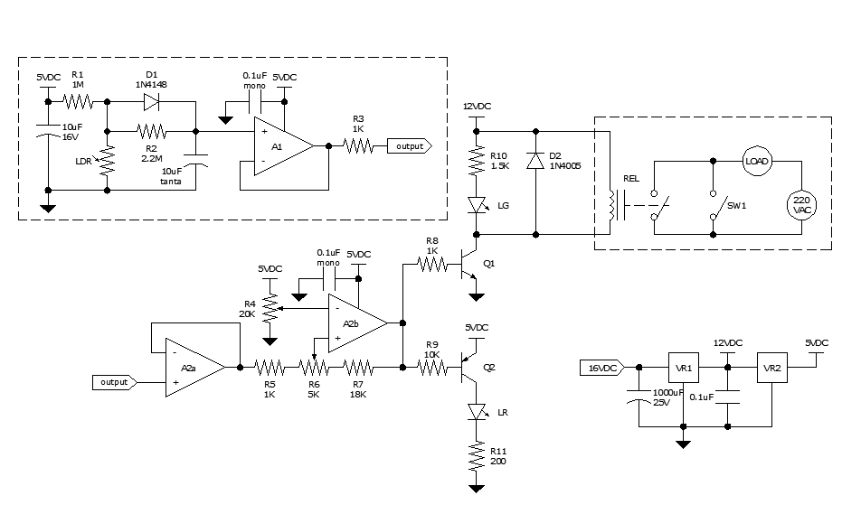
Approximately ten days ago, an all-linear automatic night light circuit was installed to control the lights in the living room. The circuit comprises three operational amplifiers (op-amps): two configured as voltage followers and one as a comparator. As depicted...
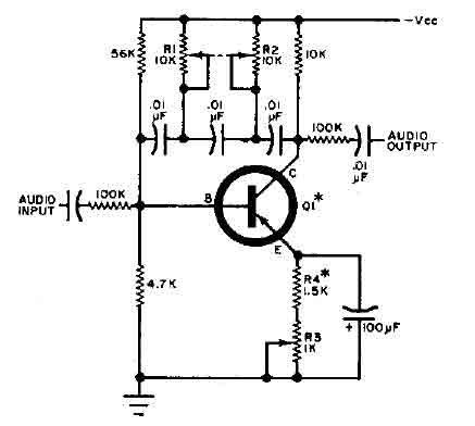
This circuit is designed for selective tuning adjustments between two closely spaced audio tones. The frequency is determined by the values of the capacitors and resistors in the feedback circuit connecting the collector and base of transistor Q1. With...
This automatic NiCd charger for 9V NiCd batteries utilizes the properties of a 555 timer and is straightforward to construct. The design allows for continuous charging of the battery without the risk of overcharging or discharging. With the specified...

This car audio amplifier circuit is based on the LA47536 audio amplifier integrated circuit designed by Sanyo. This audio amplifier circuit is specifically designed for car audio power amplifiers. The LA47536 car audio amplifier IC features four output channels...
The two circuits below illustrate the application of the 555 timer to activate a relay for a specified duration by pressing a momentary normally open (N/O) push button. The circuit on the left can be used for longer time...