
voltage Calculating current in a simple circuit

The circuit design includes a 12V power supply connected to a 12V fan that draws 70mA of current. The fan’s specifications dictate that the circuit must be capable of supplying this current consistently. A resistor is employed to ensure proper current limiting for any additional components, such as LEDs, that may be included in the circuit. The analysis of voltage drops across resistors is crucial for understanding potential issues with wiring or power supply performance.
When measuring the voltage across a resistor, it is essential to recognize that the reading reflects the voltage drop due to the current flowing through it. In this scenario, measuring 10.83V across a 10kΩ resistor indicates a current of approximately 1.83mA, which is acceptable for that resistor value. The voltage drop of 1.77V that is observed could be attributed to resistance in the wiring or a failing battery. It is advisable to calculate the total resistance in the circuit, considering the series resistance of the battery and the wiring, to ensure the circuit operates efficiently.
For the LED components, current limiting is critical to avoid exceeding their rated current. The use of a 330Ω resistor in series with each LED allows for a safe operating current of approximately 30mA, which is typical for many standard LEDs. This design choice not only ensures the longevity of the LEDs but also maintains adequate brightness levels. The choice of resistor wattage is also important; using a quarter-watt resistor is standard, but opting for a higher-rated resistor can provide additional safety and reliability in the circuit.
In summary, this circuit design effectively integrates a 12V fan and LED components while addressing critical factors such as current supply, voltage drops, and component safety, ensuring a reliable and functional electronic system.Attach a 12V fan to this circuit which draws 70mA (0. 007A), so the circuit must have at least that much current. Yes, there is something missing in the analysis. Actually there is too much in the analysis. The voltage drop across the resistor will be simply be the voltage you are putting across it, i. e. 12. 6V (or 12, 6 in your numeric language :) angelatlarge Apr 7 `13 at 4:30 The issue here is probably coming from the term "voltage drop". If you measure 10, 83 V at the resistor then your are either losing voltage to your cabling(probably not at 1ma) or you have a battery that is very near end of life and sagging a little. Your voltage "drop" on the resistor is how much the voltage changes across the resistor, not how much it changes getting their.
So 10, 83/10k is. 00183 A or 1. 83 mA, which is reasonable for a 10k resistor. Kortuk™ Apr 7 `13 at 4:47 so, for 1, 77V drop, that is happening in your cabling or battery, so if you take that drop with the current you re calculating you can determine the resistance of the cabling+series resistance of battery that is being placed with R1. I would write an answer, but someone with pictures would make a much better job then me. Kortuk™ Apr 7 `13 at 4:54 @angelatlarge, you are right. the voltage across the resistor will be the same as there is only one load, so the current will be I = V/R, I = 12.
6V / 10K = 1. 26mA. David Norman Apr 7 `13 at 5:19 @vsams14 I believe you might have some misconceptions about what voltage and current from a power supply are. this question is very detailed and might help you. If you are just asking if your power supply will work for this fan, if the fan is designed for a 12V supply you are 95% fine.
Kortuk™ Apr 7 `13 at 6:25 LEDs are current-based devices, not voltage based. In other words, the design parameter for a driving circuit is, how much current should be allowed to pass through an LED. This current limiting is frequently done by putting a resistor in series with the LED (one for each LED if several are to be used in parallel).
The current rating of the LEDs is not stated in the question. Since many common LEDs are typically rated for 20 or 30 mA, assuming 30 mA (0. 03 Amperes) for the purpose of this answer. The next higher commonly available resistor value of 330 Ohms would work well - Connecting one in series with each LED fed from the 12 Volt power rail should work fine. The higher than calculated resistor also increases the margin of safety by slightly reducing the current through the LED, without perceptibly reducing illumination.
This is pretty close to a quarter watt, one of the commonly used resistor power ratings. Therefore, for a margin of safety, a higher wattage resistor is suggested. 🔗 External reference
Related Circuits
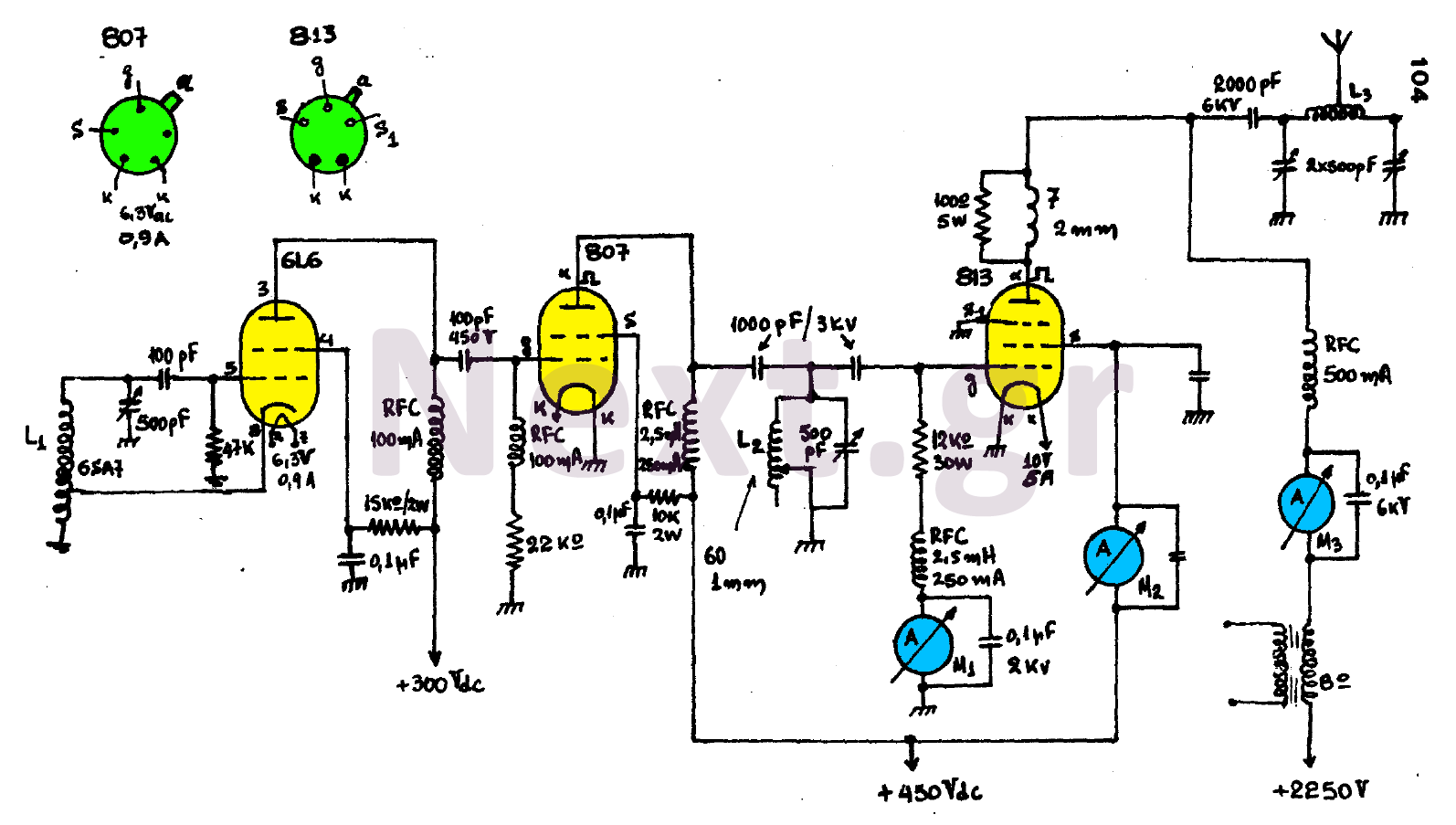
The circuit consists of three main stages and provides the antenna with a power output of 300 watts, contingent upon proper tuning. The first stage is an oscillator featuring an oscillating coil L1, which is commercially available as a...
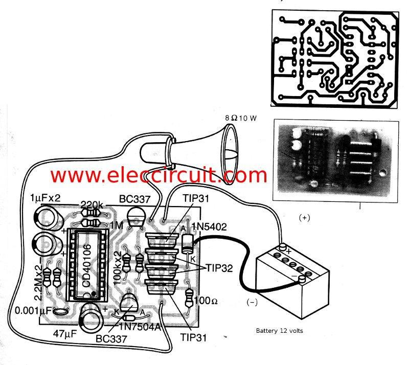
This is a simple siren sound generator with high power output and significant noise. The circuit utilizes digital ICs, specifically the CD4046, in an inverter configuration, along with four transistors to amplify the current output to a horn speaker...
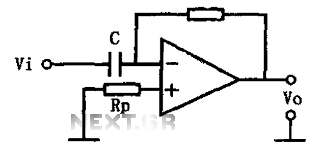
This circuit illustrates a basic differentiating circuit. The differential operation circuit can process input and output signals, establishing a relationship between the output and the input. A basic differentiating circuit is designed to produce an output that is proportional to...

When the system is placed in a shop or mall, logos and product advertisements serve as an ideal complement to temperature information. For home use, photographs of children at the beach or, should the temperature drop, images of making...
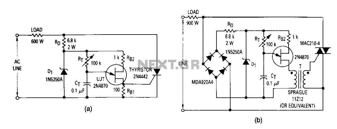
The most elementary application is a half-wave control circuit. The thyristor is acting both as a power control device and as a rectifier, providing variable power to the load during the positive half cycle and no power to the...
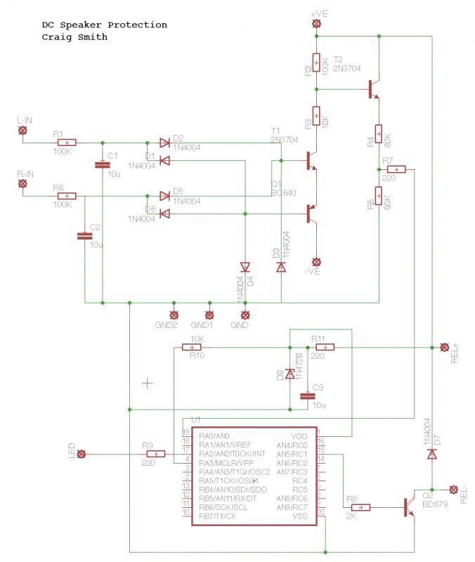
This circuit utilizes schematics from Elliot Sound Products. The left input (L-In) and right input (R-In) are connected directly to the speaker terminals, while the positive and negative voltages are supplied at +25V and -25V from the power supply....