
Check the three-phase motor with broken bars

The circuit for a three-phase motor with a broken bar inspection system typically consists of several key components that work together to monitor the health of the motor's rotor. The inspection circuit is crucial for identifying faults that could lead to reduced efficiency or catastrophic failure.
In this setup, the three-phase motor is powered by a three-phase supply, which provides the necessary torque and speed for operation. The inspection circuit includes current sensors placed in each phase line to monitor the current flowing through the motor. These sensors can be Hall effect sensors or current transformers, which provide real-time feedback on the electrical conditions of the motor.
The output from the current sensors is fed into a microcontroller or a dedicated monitoring unit. This unit processes the signals and compares the current readings against predefined thresholds. If the current in any phase deviates significantly from the expected value, it may indicate a broken bar in the rotor. The microcontroller can then trigger an alarm or an indicator light to alert maintenance personnel of the potential issue.
Additional components in the circuit may include resistors for signal conditioning, capacitors for noise filtering, and possibly an interface for communication with a supervisory control and data acquisition (SCADA) system. The design must ensure that the inspection circuit is robust enough to operate under the motor's environmental conditions, which may include vibrations and temperature fluctuations.
In summary, the three-phase motor with a broken bar inspection circuit is an essential system for ensuring reliable motor operation, minimizing downtime, and enhancing overall maintenance practices. As shown in the three-phase motor with broken bars of inspection circuit:
Related Circuits
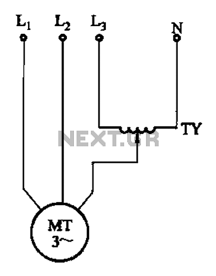
The circuit illustrated in Figure 3-175 features a regulator connected between one phase and neutral. It is designed for use with a 380V torque motor. This method offers advantages over the serious line imbalance approach, resulting in improved operating...
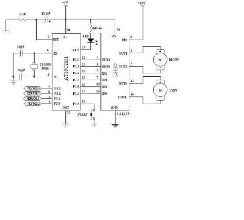
This circuit can control a small DC motor, like the one in a tape recorder. When both the points A and B are "HIGH," Q1 and Q2 are in saturation. Hence, the bases of Q3 to Q6 are grounded....
Constructing a robot, or rather a vehicle, that uses two motors. Reference materials regarding the schematics for the circuit design have been obtained, but the current schematics utilize smaller motors that draw less power and operate with a lower...
A CD4017 is configured as a senary counter, with an input clock frequency of 300 Hz. Diodes VD1 to VD9 and resistors R1 to R3 form three three-input OR gates, which can each receive two 50 Hz three-phase wave...
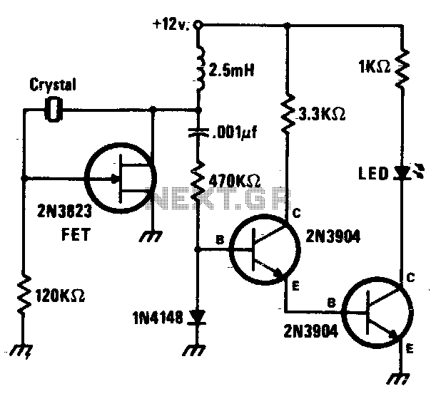
This circuit is a simple Pierce oscillator with an LED go/no-go display. The checker works best with crystals having fundamental frequencies in the seven to eight megahertz range. The Pierce oscillator circuit is a popular choice for generating high-frequency signals,...
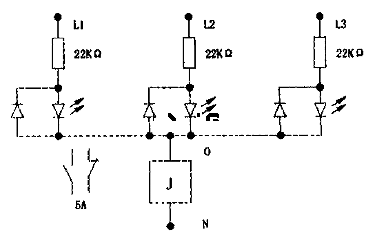
The circuit illustrated below activates a small relay (J) when there is an imbalance in any one phase of a three-phase circuit. This relay triggers an external control contact, which immediately disconnects the power supply to the main circuit...