
Crystal checker

The Pierce oscillator circuit is a popular choice for generating high-frequency signals, particularly in the range of 7 to 8 MHz, which is ideal for various applications such as RF communication and signal processing. The core of the circuit consists of an inverter or a CMOS gate configured to provide the necessary feedback for oscillation.
In this configuration, a quartz crystal is connected between the output and the input of the inverter, establishing a resonant circuit that determines the oscillation frequency. The LED go/no-go display is integrated into the circuit to provide a visual indication of the oscillator's operation. When the oscillator is functioning correctly, the LED will illuminate, signaling that the circuit is oscillating at the desired frequency. Conversely, if the LED remains off, it indicates that the oscillator is not functioning, which may be due to issues such as incorrect crystal selection, improper connections, or component failures.
The circuit typically includes a few passive components such as resistors and capacitors, which help to stabilize the oscillation and set the amplitude of the output signal. The choice of these components, along with the crystal, will significantly affect the performance and stability of the oscillator. Proper layout and grounding techniques are also essential to minimize noise and interference, ensuring reliable operation in practical applications.
Overall, this simple Pierce oscillator design with an LED indicator serves as an effective tool for testing and verifying the functionality of quartz crystals within the specified frequency range.This circuit is a simple Pierce oscillator with an LED go/no go display Checker works best with crystals having fundamental frequencies in the seven to eight megahertz range.
Related Circuits
Transistor Q1, a 2N3563, and its associated components form an oscillator circuit that will oscillate if, and only if, a good crystal is connected to the test clips. The output from the oscillator is then rectified by the 1N4148...
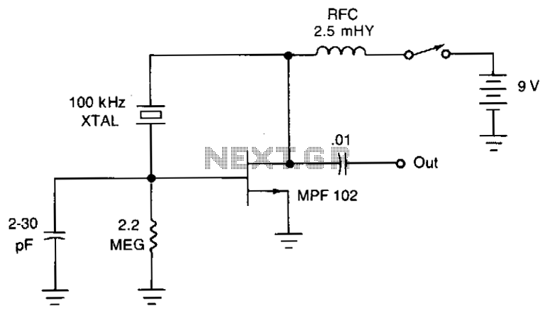
The JFET Pierce oscillator is stable and straightforward. It can serve as the clock for a microprocessor, a digital timepiece, or a calculator. With a probe connected to the output, it can function as a precise injection oscillator for...
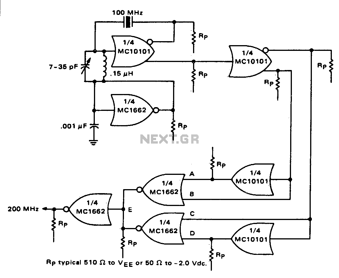
One section of the MC10101 is configured as a 100 MHz crystal oscillator, with the crystal placed in series within the feedback loop. An LC tank circuit is utilized to tune the 100 MHz harmonic of the crystal, which...
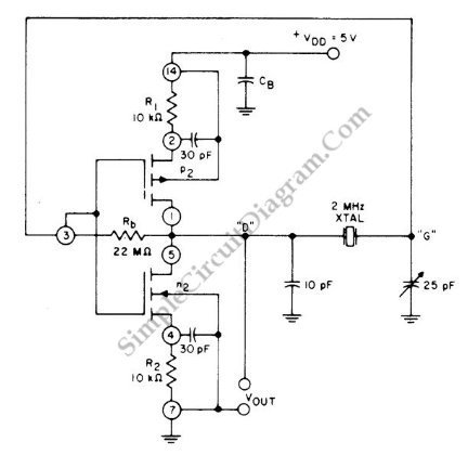
This is a 2 MHz crystal circuit utilizing a CMOS pair. This circuit is suitable for applications in digital watches and clocks due to its low power consumption. The 2 MHz crystal oscillator circuit employs complementary metal-oxide-semiconductor (CMOS) technology, which...
The RF engineer sometimes needs an instrument that can reliably and quickly test a low-frequency quartz crystal unit. Finding such equipment can be challenging, and engineers often refer to electronic circuit handbooks for schematics that can perform this task....
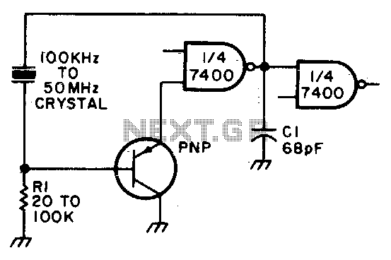
Adjust Rl for approximately 2 volts at the output of the first gate. Additionally, adjust Cl for optimal output. In the context of electronic circuit design, the output voltage of a gate, such as a logic gate or operational amplifier,...