
Chime Circuit with 4049

The circuit utilizes a square wave generator formed by the combination of resistor R1 and capacitor C1, alongside two converters, which serve to produce a basic tone. The inverter following this generator plays a dual role: it acts as a buffer, isolating the generator from the subsequent stages, and as a driver, providing the necessary current to the load, specifically the President component, which may refer to a specific electronic device or module within the system.
Resistor R2 is critical in this configuration, with its minimum resistance value set at 100 ohms. This resistor is strategically placed to limit the power delivered to the circuit, thereby controlling the overall volume of the output signal. This feature is essential for ensuring that the generated tone does not exceed desired levels, which could lead to distortion or damage to connected components.
The pulse generator circuit comprises diode D1, capacitor C2, resistors R3 and R4, and two additional inverters. This combination is responsible for shaping the output waveform and determining the rise and fall times of the signal, which are crucial for the performance of the ring. The timing characteristics of this pulse generator directly influence the auditory experience of the carillon, affecting how quickly it reaches its peak amplitude and how gradually it decays.
Furthermore, the circuit formed by the decomposition of components D2, C3, R5, and Q serves to reduce the amplitude of the carillon sound exponentially over time. This design is particularly useful in applications where a gradual fading of sound is desired, creating a more natural auditory experience. By incorporating these elements, the circuit achieves a refined control over sound dynamics, contributing to the overall functionality and performance of the electronic system.Resistor R1, capacitor C1, and two converters form a square wave generator, which produces the basic tone. The generator is sui followed by an inverter which serves as both a buffer and a driver for the President.
The resistor R2, which has a minimum value of 100 ohms, limits the power and volume controls. The diode D1, capacitor C2, resistors R3 and R4, and two in converters to create the pulse generator which determines the power-up and decay times of the ring. The circuit formed by decomposition of D2, C3, R5, and Q-reduces the amplitude of the carillon exponentially with time.
Related Circuits
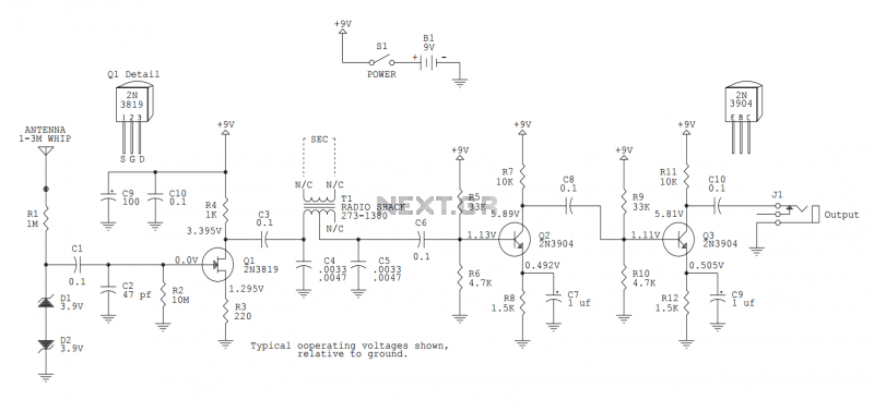
This version sports a 2nd audio amplifier stage at Q3. The output level with this version is sufficient to drive a crystal headphone to a comfortable volume. The "crystal" headphone is like those used on ye olde crystal radios....
Can someone please help explain how this circuit works? I am confident that I understand how the voltage divider network operates. The circuit in question likely includes a voltage divider configuration, which is a fundamental concept in electronics used to...
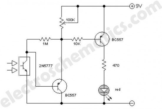
This enhanced infrared detector is designed for use with commercial infrared remote control handsets. This compact circuit is effective for quick go/no-go applications. The infrared detector circuit is engineered to respond to signals emitted by infrared remote control devices, commonly...
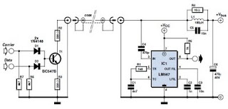
This circuit was designed to transmit commands over an LNB coaxial cable. An LNB (Low-Noise Block downconverter) is commonly used for satellite TV reception and is positioned at the focal point of a satellite dish. The circuit generates a...
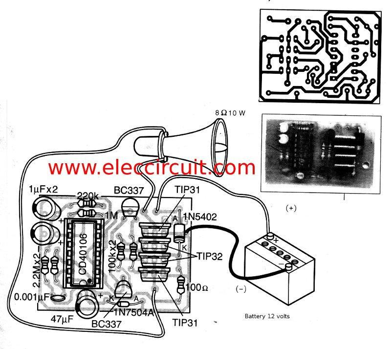
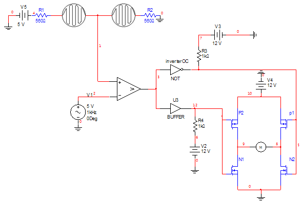
This is a simple siren sound generator with high power output and significant noise. The circuit utilizes digital ICs, specifically the CD4046, in an inverter configuration, along with four transistors to amplify the current output to a horn speaker...
This digital DIY tachometer for bicycles utilizes two reed switches to gather speed information. The reed switches are positioned near the wheel rim, where permanent magnets are mounted on the wheel spokes. As the spokes rotate, the magnets pass...