
Digital Bike Tachometer Circuit

This digital DIY tachometer circuit is designed to provide an accurate speed measurement for bicycles using a straightforward and effective mechanism. The integration of two reed switches allows for reliable detection of the wheel's rotation as the permanent magnets pass by. This approach minimizes mechanical wear and enhances the durability of the system. The use of two 4026 ICs enables efficient pulse counting and decoding, which is essential for translating the mechanical motion into a readable digital format.
The anti-bounce feature provided by the RS flip-flops U3 and U4 is crucial for ensuring that only valid pulses are counted, thereby improving the accuracy of speed readings. Gate U7 facilitates the flow of pulses to the counting mechanism, ensuring that the system responds promptly to the activation of the reed switches. The monostable multivibrator configuration using U5 and U6 is particularly beneficial, as it allows the user to set the measurement interval, thus accommodating different types of bicycles and riding conditions. The inclusion of potentiometer P1 for calibration purposes ensures that the tachometer can be fine-tuned for optimal performance.
The design prioritizes battery efficiency by activating the circuit only when needed, which prolongs battery life and reduces the frequency of replacements. The requirement for at least three permanent magnets ensures that the system receives sufficient input for accurate speed calculations, while also allowing for a margin of error in the event that one magnet does not trigger a reed switch. The ability to calibrate the circuit using a pre-calibrated tachometer adds a layer of precision, making this DIY project suitable for hobbyists and cycling enthusiasts who seek to enhance their biking experience with reliable speed measurements.This digital DIY tachometer for bikes uses two reed switches to get the speed information of the bicycle. The reed switches are installed near the rim of the wheel where permanent magnets pass by. The permanent magnets are attached to the wheelspokes and activate the reed switches everytime they pass by it.
The speed is digitally displayed. The ta chometer circuit works according to this principle; the pulses created by the reed contacts are counted within a certain time interval. The resulting count is then displayed and represents the speed of the bike. Two 4026 ICs are used to count the pulses, decode the counter and control two 7-segment LED display. RS flip-flops U3 and U4 function as anti-bounce. The pulses arrive at the counter`s input through gate U7. The measuring period is determined by monostable multivibrator U5/U6 and can be adjusted through potentiometer P1 so that the tacho can be calibrated.
The circuit U1/U2 resets the counters. Since batteries are used to power the circuit, it is not practical to support the continous display of speed information. This circuit is not continously active. The circuit is activated only after a button is pressed. At least three permanent magnets must be installed on the wheel. The circuit can be calibrated with the help of another precalibrated tachometer. 🔗 External reference
Related Circuits
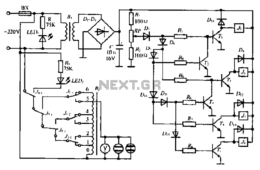
A step-down transformer converts AC 220V to a lower voltage. A diode bridge rectifier and filter capacitor provide a direct current (DC) output, which fluctuates with variations in the grid voltage. A resistive voltage divider is used for sampling....
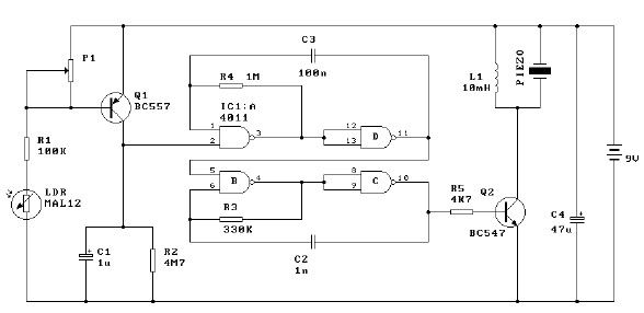
This light alarm schematic circuit is designed using common electronic components, as illustrated in the circuit diagram below. The light alarm circuit will activate an alarm as soon as the drawer is opened and light falls on the Darlington...
This circuit provides an initial voltage of 2.5V per cell to quickly charge a car battery. The charging current decreases as the battery charges, and when the current drops to 180 mA, the charging circuit reduces the output voltage...
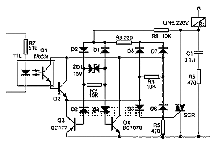
The relay illustrated in the figure operates based on non-inductive analog circuit theory. Its working principle involves a 220V power supply connected to a load (RL), resistors (R1, R3, R6), diodes (D1 to D8), and a zener diode (ZD1)....
For example, I do not understand the process of demodulation or the modulation itself, and so on. Is there someone who can understand this circuit? Could you please assist me? The circuit in question likely involves a modulation and demodulation...
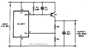
The IC8211 serves as a voltage reference and regulator amplifier, with Q1 likely functioning as the series pass transistor. R1 determines the output current of the IC8211, while C1 and C2 contribute to loop stability and help suppress the...