
Church bell Controller with ATmega32
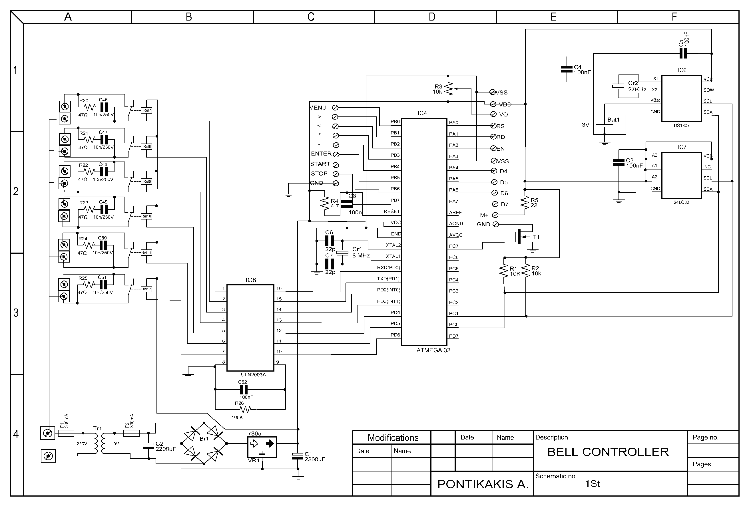
This church bell controller circuit utilizes an ATmega32 microcontroller as its central processing unit, which is responsible for executing the programmed firmware. The microcontroller interfaces with a 24LC32 EEPROM, providing non-volatile storage for user-defined melodies, settings, and operational parameters. The system features a 4x20 LCD display for user interaction, allowing for a comprehensive menu-driven interface.
User input is facilitated through six tactile push buttons, which include functions for navigating the menu (Menu, Up, Down), confirming selections (Enter), and controlling the bell operation (Start, Stop). The firmware, written in C, is designed to be modular, with the potential for future enhancements without exceeding the 30 Kbyte flash memory limit of the microcontroller.
The circuit supports over 75 different melodies, which can be selected and programmed by the user. An integrated real-time clock (RTC) functionality is provided using a DS1307 chip, which ensures accurate timekeeping and includes a backup battery to maintain time during power outages. The system generates a pulse of 1 second every minute for the electromechanical clock, ensuring synchronization with real time.
Additional features include automatic correction for time loss during power outages, manual adjustments for the clock, and the ability to silence the bells during designated hours, accommodating for quiet periods in tourist areas. The user can modify the rhythm of the bells, and these settings are stored in the EEPROM for persistent memory retention.
The circuit is capable of controlling up to five bells and one clock, providing flexibility in operation. Overall, this church bell controller circuit combines robust functionality with user-friendly operation, making it a versatile solution for managing bell chimes in various settings.This circuit is a church bell controller. Basic component is an ATmega32 microcontroller. At the circuit 1 24LC32 eeprom memories is being used. As control I created a menu who will be appeared on 4x20 LCD (Liquid Crystal Display). The menu browsing can be done by 6 buttons at the face of the circuit's box (Menu, Up, Down, Enter, Start, Stop). The all firmware binds about 30Kbytes flash memory and can be increased by adding new features-functions.
This program has been written in C with CVAVR compiler. The idea of this circuit is being given by a friend of mine who has an foundry and he is building bells. I have made the PCB by my self. Features 1. More 75 different melodies (ADAM, PANYGJRJKO, AGJORJKO, etc) 2. Control of electrometrical clock of church with the production of pulse of duration 1Sec each one minute. 3. Automatic correction in case of power loss. 4. Percussion of clock each half but also entire hours, with possibility of choice of hours of silence (for tourist regions and hours of common quietness).
5. Manual correction of electromechanical clock. 6. All regulations become with the help of guidance (menu, up, down, enter, start, stop) 7. When it runs a rhythm we have the possibility of increase or decrease her speed, the information will stored in memory 24LC32. 8. Display time (DS1307), with backup battery. 9. All the in formations are displayed on 4X20 LCD. 10. Control up to 5 bells and 1 clock. 11. The user create his own program 🔗 External reference
Related Circuits
The ding-dong electronic doorbell circuit consists of a power supply circuit, a trigger control circuit, and an audio oscillator output circuit. The power supply circuit includes a power transformer (T), rectifier diodes (VD1-VD4), and a filter capacitor (C1). The...
This DC Motor Controller circuit will control a 12V dc motor. The system will have three pushbuttons: a START button, a REVERSE button and a STOP button. Initially, the motor must not be running. When the START button is...
This temperature controller functions as a pulse snatching device, enabling it to operate at its own speed and activate at the zero crossing of the line frequency. The zero crossing activation minimizes the generation of line noise transients. A...
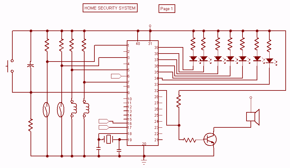
Security is a prime concern in our day-to-day life. Everyone wants to be as much secure as possible. An access control for doors forms a vital link in a security chain. The Microcontroller based Home Security System can be...

Combining armature resistance cancellation through positive current feedback with a motion-reversing H-bridge circuit topology introduces an innovative approach to DC servo motor speed control. The integration of armature resistance cancellation in DC servo motors is a significant advancement in enhancing...
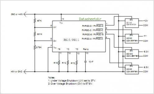
The PS10 saves board space, improves accuracy, eliminates optocouplers or level shifts, and reduces overall component count by combining four programmable timers, input under-voltage (UV) and over-voltage (OV) supervisors, a programmable power-on reset (POR), and four 90V open drain...