
church bell with timer and LCD

More: Features
1. More 32 different melodies (ADAM, PANYGJRJKO, AGJORJKO, etc)
2. Control of electrometrical clock of church with the production of pulse of duration 1Sec each one minute.
3. Automatic correction in case of power loss.
4. Percussion of clock each half but also entire hours, with possibility of choice of hours of silence (for tourist regions and hours of common quietness).
5. Manual correction of electromechanical clock.
6. All regulations become with the help of guidance (menu, up, down, enter, start, stop)
7. When it runs a rhythm we have the possibility of increase or decrease her speed, the information will stored in memory 24LC32.
8. Display of temperature (DS1621).
9. Display time (DS1307), with backup battery.
10. All the information are displayed on 4X20 LCD.
11. Control up to 6 bells.
This church bell controller circuit utilizes an ATmega32 microcontroller as the central processing unit, which manages the operation and functionality of the system. The circuit is equipped with two 24LC32 EEPROM memories; one is dedicated to storing internal standard melodies while the other is reserved for user-generated compositions, a feature that is planned for future implementation.
User interaction with the system is facilitated through a 4x20 LCD (Liquid Crystal Display) that presents a menu-driven interface. The menu navigation is controlled by six tactile buttons located on the front panel of the circuit's enclosure, labeled as Menu, Up, Down, Enter, Start, and Stop. This design allows users to easily navigate through various settings and options. The firmware, written in C using the CVAVR compiler, occupies approximately 19 kilobytes of flash memory, with the potential for expansion to incorporate additional features.
The circuit supports a repertoire of over 32 different melodies, including titles such as ADAM, PANYGJRJKO, and AGJORJKO, enhancing its versatility for different church settings. It also integrates functionality for controlling an electromechanical clock, generating a pulse of one second duration every minute, which is crucial for accurate timekeeping.
In the event of a power loss, the system is designed to automatically correct the clock, ensuring continued accuracy. The controller can also produce chimes at both half and full hours, with the option for users to set specific hours of silence, catering to the needs of tourist regions and quiet hours.
Manual adjustments to the electromechanical clock are possible, providing flexibility in maintaining accurate time. The menu-driven interface allows for intuitive regulation of all settings, including the ability to increase or decrease the rhythm speed of the melodies, with all adjustments stored in the 24LC32 memory.
Additional features include the display of temperature using a DS1621 sensor and real-time clock functionality provided by a DS1307 chip, which is supported by a backup battery to maintain timekeeping during power outages. All relevant information is presented clearly on the 4x20 LCD, ensuring users can easily access and monitor the system's status. The circuit is capable of controlling up to six bells, making it suitable for various church sizes and requirements.This circuit is a church bell controller. Basic component is an ATmega32 microcontroller. At the circuit 2 24LC32 eeprom memories is being used, the 1st for internal standard melodies and the 2nd one is for user's compositions. This feature will be provided in the future. As control I created a menu who will be appeared on 4x20 LCD (Liquid Crystal Display). The menu browsing can be done by 6 buttons at the face of the circuit's box (Menu, Up, Down, Enter, Start, Stop).
The all firmware binds about 19Kbytes flash memory and can be increased by adding new features-functions. This program has been writen in C in CVAVR compiler. The idea of this circuit is being given by a friend of mine who has an foundry and he is building bells.
I have made the PCB by my self. Features 1. More 32 different melodies ( ADAM, PANYGJRJKO, AGJORJKO, etc) 2. Control of electrometrical clock of church with the production of pulse of duration 1Sec each one minute. 3. Automatic correction in case of power loss. 4. Percussion of clock each half but also entire hours, with possibility of choice of hours of silence (for tourist regions and hours of common quietness).
5. Manual correction of electromechanical clock. 6. All regulations become with the help of guidance (menu, up, down, enter, start, stop) 7. When it runs a rhythm we have the possibility of increase or decrease her speed,the information will stored in memory 24LC32. 8. Display of temperature (DS1621). 9. Display time (DS1307), with backup battery. 10. All the in formations are displayed on 4X20 LCD. 11. Control up to 6 bells. 🔗 External reference
Related Circuits
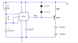
A TV remote jammer circuit using the NE555 timer IC. This device allows users to watch their favorite TV channels without interruptions, as it prevents others from changing the channel using a remote control when the circuit is activated....
The following schematic diagram is a four-hour timer circuit. Features include ease of construction, a total timing duration of 3 hours and 53 minutes, and a 9V supply voltage. Components utilized in the circuit are a 555 timer IC,...
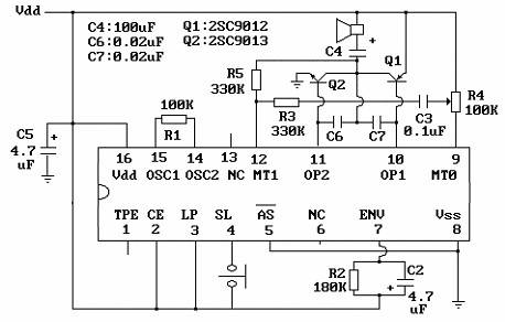
The core component of this circuit is the UM3481 integrated circuit (IC), which operates with a 1.5-volt battery. It is suitable for applications such as electronic doorbells, toys, melody clocks, and music boxes. The UM3481 is engineered to play...
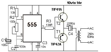
12V power inverter circuit utilizing a 555 timer for an electronic project. The 12V power inverter circuit is designed to convert a DC voltage of 12 volts into an AC voltage suitable for powering small electronic devices. The core component...
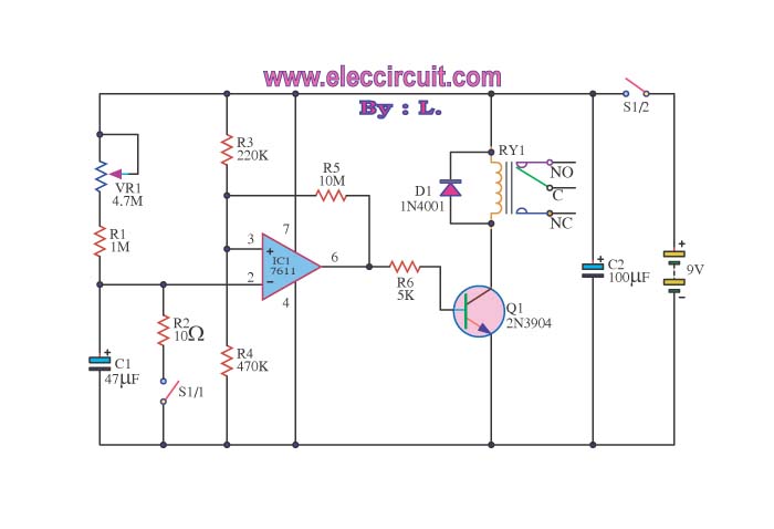
When switch S1/2 is activated, it powers the circuit C1, which utilizes the UA741 operational amplifier for voltage comparison. Pin 3 serves as the non-inverting input, while pin 2 is the inverting input. The voltage at pin 3 is...
A well-designed circuit that automatically turns off if the pushbutton is held down or jammed for an extended period. It is not re-triggerable while the light remains on. The circuit initially starts at full brightness and gradually dims to...