
TV REMOTE JAMMER CIRCUIT USING 555 TIMER

The TV remote jammer circuit primarily utilizes the NE555 timer IC configured in astable mode to generate a continuous square wave output at the desired frequency. The choice of resistors and the capacitor in the timing network is crucial as it directly influences the frequency of oscillation. In this configuration, RA and RB set the charge and discharge times of the capacitor, thereby establishing the frequency of the output waveform.
The PNP transistor SK100 is selected for its ability to handle the current required to drive the IR LED. When the NE555 output goes low, it turns on the transistor, allowing current to flow through the IR LED. This LED is designed to emit infrared light at the specified frequency of 12 kHz, which effectively disrupts the communication between the TV remote and the television set.
The overall design of the circuit is straightforward, making it accessible for hobbyists and those interested in electronics. The components required are inexpensive and readily available, allowing for easy assembly. Safety precautions should be taken into account when constructing and operating the circuit, particularly concerning the power supply and handling of electronic components. The jamming effect can be tested by attempting to use a remote control in the vicinity of the circuit to observe the disruption in functionality.A Tv remote jammer circuit, using NE555 timer IC. By using this you can watch your favorite TV channel without any interruptions. Ie; No one can be able to change the channel by means of remote, if the circuit remains ON. The circuit is simple to make at your own home, with very low cost. Let`s go deeply into the specification and requirem ents of this Project. This TV remote jammer is working on the basis, the IR rays emitted from the remote is interrupted continuously by means of this circuit. The normal operating frequency range of a TV remote is 38KHz. This circuit produces a frequency of about 12KHz. The 12KHz frequency is generated by the help of NE555 timer IC, the frequency is determined by the network consisting of RA RB and C; 10K, 1K, and 0.
01uF respectively. The output taken from the IC is given directly to a current driving PNP transistor, SK100. The transistor act as a switching network, it goes into conduction whenever the output of IC drives into negative going cycle. The conduction of transistor switch ON the IR led and emits IR rays of frequency 12Khz. This may interfere with the rays emitted from TV remote, which makes it disabled. 🔗 External reference
Related Circuits
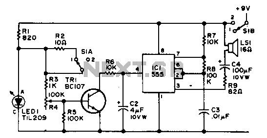
The integrated circuit (IC) operates as an astable multivibrator that is controlled by an external transistor. S1A/B serves as the on-off toggle switch. The astable multivibrator configuration is commonly utilized in various applications, including pulse generation, clock signals, and LED...

In this circuit, an additional exclusive-OR gate is connected after the modulo-2 feedback, with CI and R2 applying the supply turn-on ramp into the feedback loop. This provides sufficient transient signal so that the PRBS generator can self-start during...
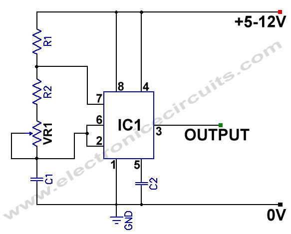
555 Variable Frequency Square Wave Generator. This simple 555 Variable Frequency Square Wave Generator produces a variable frequency output. The 555 Variable Frequency Square Wave Generator is a versatile circuit that utilizes the 555 timer IC to generate square wave...
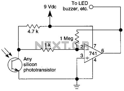
This circuit represents one of the simplest infrared (IR) receivers that can be constructed. The components are inexpensive, the layout is not critical, and a 9-V battery provides a long operational life. The described IR receiver circuit typically consists of...
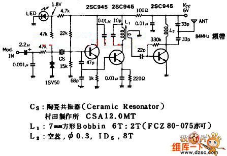
The quartz crystal oscillator circuit is highly advantageous in terms of frequency stability. Even the Voltage-Controlled Crystal Oscillator (VCXO) circuit, which allows for significant frequency changes, typically experiences only about a 1% variation. However, the linear range of control...
These ultrasonic circuits are all quite old: my notes date them at mid-70s so they don’t use ICs. Nevertheless there are several places where an op-amp would possibly simplify things. Despite their age I hope they are of interest:...