
12V power inverter using 555 timer circuit

The 12V power inverter circuit is designed to convert a DC voltage of 12 volts into an AC voltage suitable for powering small electronic devices. The core component of this inverter is the 555 timer IC, which is configured in astable mode to generate a square wave signal. This square wave signal is crucial for driving the output stage of the inverter, which typically consists of a transformer and a pair of transistors.
In this configuration, the 555 timer generates a frequency that is determined by the resistors and capacitors connected to it. The output of the 555 timer is fed into the base of the transistors, which act as switches. When the timer output goes high, it turns on one transistor, allowing current to flow through the primary winding of the transformer in one direction. When the output goes low, the other transistor is turned on, reversing the current flow through the transformer. This alternating current (AC) in the transformer's secondary winding produces the desired output voltage.
The transformer is selected based on the required output voltage and power rating. A step-up transformer is commonly used to increase the voltage from the 12V input to a higher AC voltage, typically around 120V or 230V, depending on the application's requirements.
Additional components, such as diodes and capacitors, may be included in the circuit for protection and filtering purposes, ensuring stable operation and reducing voltage spikes. A heat sink may also be added to the transistors to dissipate heat generated during operation, enhancing reliability.
This inverter circuit is suitable for various applications, including powering small household appliances, LED lights, and other low-power devices, making it a versatile project for electronics enthusiasts and engineers.12V power inverter circuit using 555 timer circuit electronic project. 🔗 External reference
Related Circuits
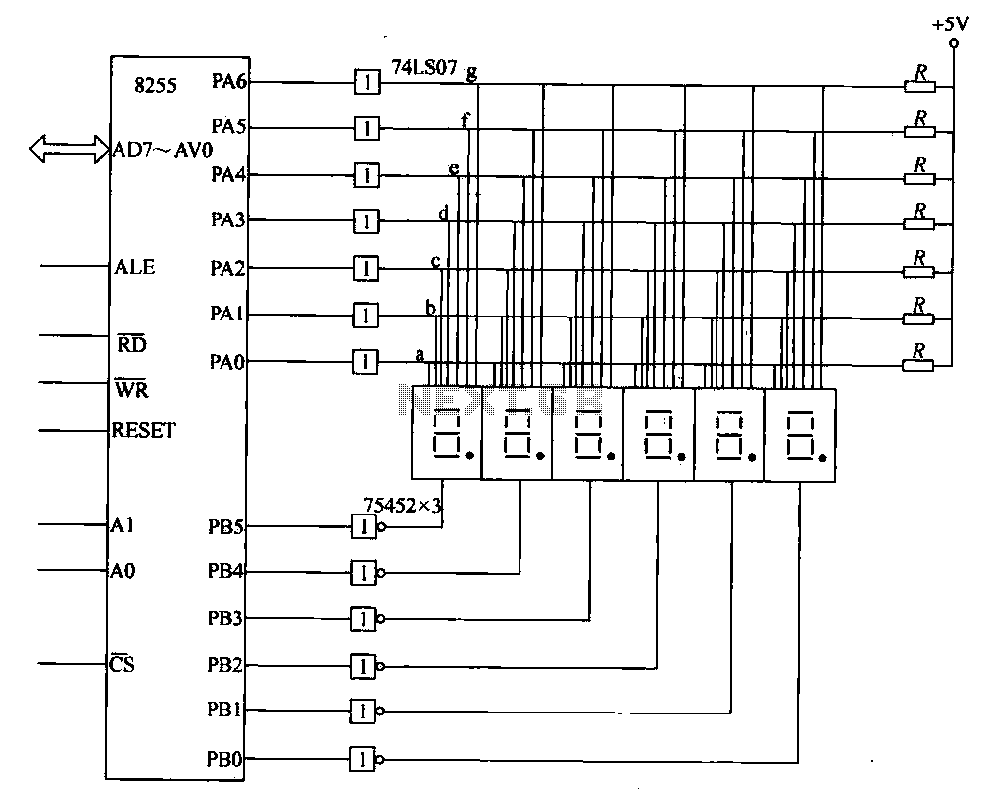
This circuit demonstrates a typical six-digit dynamic display configuration. It utilizes the PA 8255 for display output code and the PB port for bit selection code. The display buffer is designated as DISBUF, which processes the hexadecimal number obtained...
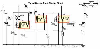
Timer garage door circuit schematic diagram, printed circuit board. The timer garage door circuit is designed to automate the opening and closing of a garage door based on a predetermined time interval. The schematic diagram illustrates the layout and connections...
LED sequencer that follows the rhythm of music or speech, powered by a 9V battery, is a portable unit. The basic circuit illuminates up to ten LEDs in sequence, following the beat. The LED sequencer circuit operates by detecting audio...

A simple technique for measuring frequencies across a wide range with acceptable accuracy limits using a PC is presented. This method follows the basic principle of measuring low frequencies, where the period of a complete wave is measured and...
Micropower and low-voltage operational amplifiers enable the construction of high-performance analog signal processors that do not require batteries or wall transformers. Instead, a capacitor can serve as the power source. The circuit illustrated in Figure 1 depicts an analog...
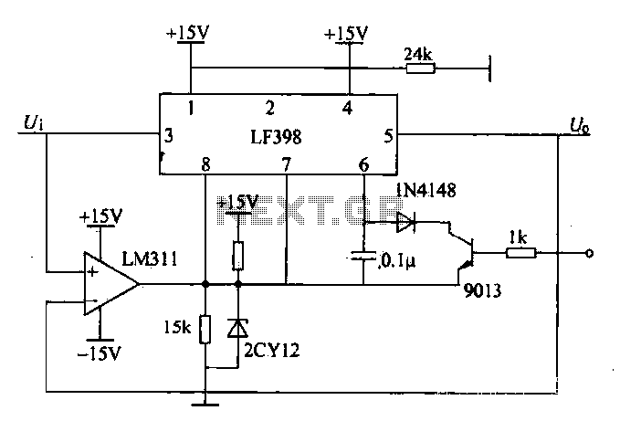
The peak voltage sample and hold circuit is illustrated in Figure 12-50. This circuit comprises the LF398 sample and hold chip and the LM311 voltage comparator. The LF398 is responsible for outputting and inputting voltages. The LM311 compares the...