
CIRCUIT CREATOR- Schematic & PCB Design
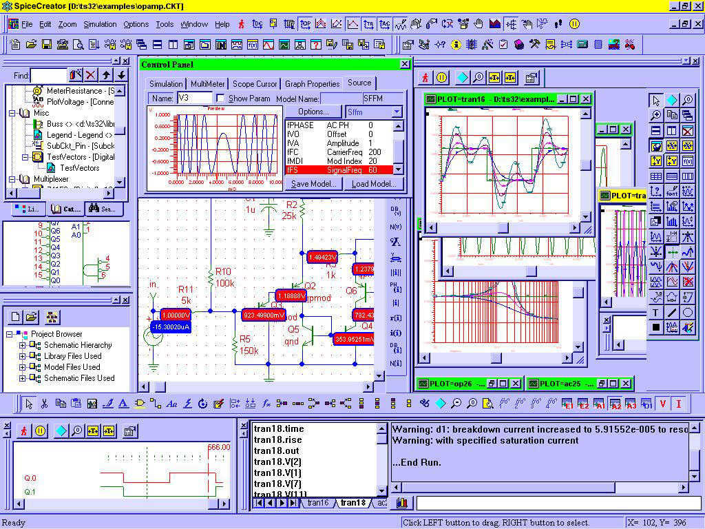
The Circuit CREATOR Electronics CAE System is a comprehensive software suite designed for electronic circuit design, tailored for use on personal computers. This system encompasses several key functionalities essential for modern electronic design workflows.
The PCB DESIGN feature includes a layout editor that allows users to create detailed printed circuit board layouts. This tool facilitates the arrangement of electronic components on the board, ensuring optimal space utilization and signal integrity. The Schematic Capture software tool enables users to create and edit circuit schematics, providing a visual representation of the electrical connections and components involved. This function is critical for validating circuit design before physical implementation.
The system supports full Schematic Design and Capture, which allows for the development and documentation of complex electronic circuits. This capability is complemented by Circuit Simulation, enabling users to test and analyze circuit behavior under various conditions. This simulation feature is crucial for identifying potential issues and optimizing circuit performance prior to prototyping.
Additionally, the full interactive Symbol Editor allows users to create and modify component symbols used in schematics, ensuring that all components accurately represent their physical counterparts. The professional Printed Circuit Board Design and Layout tools provide advanced features for designing high-quality PCBs, including layer management, design rule checks, and visualization tools.
Automatic Routing functionality streamlines the process of connecting components on the PCB, significantly reducing design time and minimizing human error. This feature intelligently determines the best paths for traces, ensuring efficient routing while adhering to design constraints.
Overall, the Circuit CREATOR Electronics CAE System offers an integrated solution that enhances productivity and accuracy in electronic design, making it an invaluable tool for engineers and designers in the field.Circuit CREATOR Electronics CAE System provides the most complete and high performance solution for electronics design using personal computers. Includes PCB DESIGN -layout editor and Schematic Capture software tool, full Schematic Design and Capture, Circuit Simulation, full interactive Symbol Editor, professional Printed Circuit Board Design and Layout, and Automatic Routing. All in a Single 🔗 External reference
Related Circuits
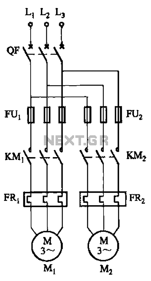
The circuit illustrated in Figure 3-64 operates with switch SA1 in the work position and switch SA2 in the standby position, allowing motor Mi to run while motor Mz remains on standby. In the event of downtime for motor...
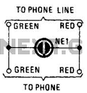
A neon lamp can easily be added to the phone line to act as a ring indicator. It is perfect for times when you cannot hear the phone. The integration of a neon lamp as a ring indicator in a...
The task involved testing the capacitive properties of food by connecting various edibles to an Arduino. This project, known as BeetBox, was developed by Scott Garner, a student at NYU-ITP, who designed an innovative musical instrument that uses beets...
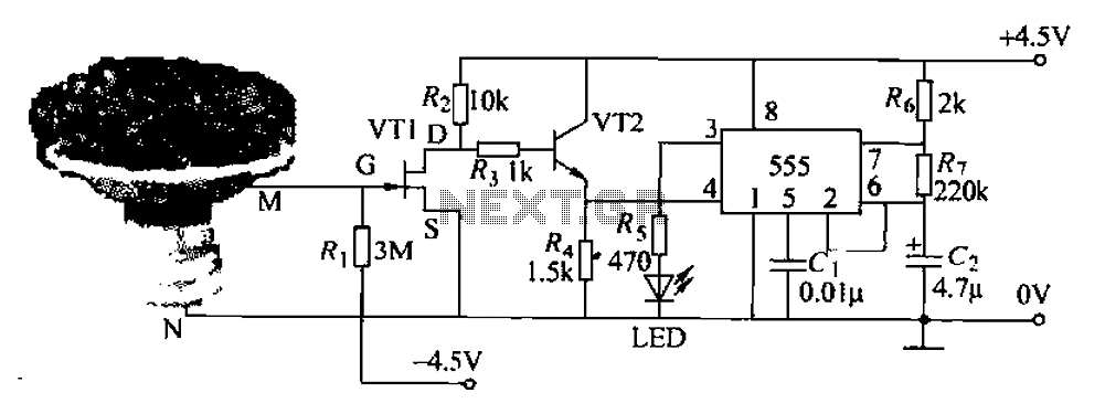
The flowers in pots require watering, as relying solely on the observation of moist soil surfaces can be unreliable. To address this issue, a flower watering indicator has been developed. This circuit includes a field effect transistor (VT1), a...
The PCA84C-440/441 is a single-chip microcomputer integrated circuit produced by Philips. It is widely utilized in both domestic and imported large screen color televisions, including those manufactured by Philips and other brands. The PCA84C-440/441 IC is housed in a...
This circuit is a modified Hartley oscillator that incorporates additional components. It utilizes a small audio transformer, specifically the LT700 model. The primary winding is center-tapped with an impedance of 1 kΩ at 1 kHz, while the secondary winding...
Warning: include(partials/cookie-banner.php): Failed to open stream: Permission denied in /var/www/html/nextgr/view-circuit.php on line 713
Warning: include(): Failed opening 'partials/cookie-banner.php' for inclusion (include_path='.:/usr/share/php') in /var/www/html/nextgr/view-circuit.php on line 713