
Electronic Canary Circuits

The modified Hartley oscillator circuit is designed to generate audio frequency signals characterized by a distinctive chirping sound. The core of the circuit is the audio transformer, LT700, which facilitates signal amplification and impedance matching. The center-tapped primary winding allows for a balanced operation, enhancing the oscillator's stability and efficiency. The impedance values indicate that the circuit is optimized for audio applications, typically operating within the range of 1 kHz.
The inclusion of R1 and C1 serves a dual purpose. R1 not only provides biasing for the transistor but also influences the charging and discharging time constants of the capacitor C1. The 100 µF capacitor plays a critical role in determining the oscillation frequency; as it charges through the 4.7 kΩ resistor, the voltage across it increases until it reaches a threshold that allows the transistor to conduct. When the transistor is cut off, the oscillation halts, and the capacitor discharges through the base-emitter junction, reinitiating the oscillation cycle.
The frequency of the chirp can be adjusted by varying the values of R1, C1, or the charging resistor, thus providing a means to tailor the output frequency for specific applications. The chirp's frequency is also influenced by the supply voltage, making the circuit adaptable to different power sources. The push-button switch serves as a control mechanism, allowing the user to initiate the charging of the capacitor; upon release, the rapid decay of oscillation leads to an increase in chirp frequency, creating a dynamic audio effect.
Overall, this modified Hartley oscillator circuit exemplifies a versatile design that can be utilized in various audio applications, including sound effects generation, alarm systems, and other creative electronic projects.This circuit is a modified Hartley oscillator with a couple of extra components included. The transformer is a small audio transformer, type LT700. The primary is center tapped with an impedance of 1Kohms at 1KHz. The secondary has an impedance of 8 ohms. The inclusion of R1 and C1 give this oscillator its characteristic "chirp". As the 100u capa citor charges via the 4. 7K resistor, R1 the bias for the transistor is cut off. This causes the oscillation to stop, the capacitor discharges through the base emitter circuit of the transistor and oscillations start again. Altering these components alters the frequency of the chirp. The chirp is also voltage dependent. When the push button switch is operated the 100u capacitor is charged. When its released, the oscillation decays and the chirp becomes faster. 🔗 External reference
Related Circuits

One interface that is missing in the Lego MindStorms system is an electronic ear. This does not imply that the RCX should respond to spoken commands, which would require extensive electronics and software. Instead, it would be beneficial if...

This is a simple and cost-effective solar battery charger that can be constructed by hobbyists. It has some limitations compared to other similar controllers, but it also provides several benefits. While primarily designed for charging lead-acid batteries, it can...

This circuit includes a 2048 radio remote control transmitter and a corresponding wireless receiver that features high reception sensitivity and low power consumption. The combination of these two components provides a highly reliable remote control system, suitable for various...
For successful circuit-building exercises, follow these steps: Measure and record all component values before constructing the circuit, selecting resistor values that are sufficiently high to minimize the risk of damaging any active components. In case of significant errors (greater...
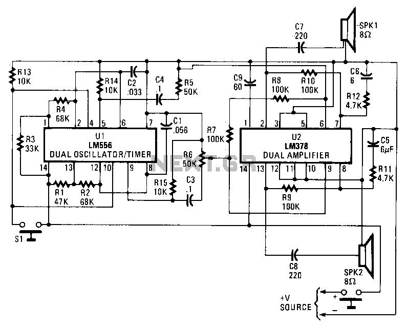
An LM556 dual oscillator/timer, U1, is configured as a two-tone oscillator that drives U2, a dual 4-watt amplifier. One of the oscillators, connected to pins 1 to 6 of U1, generates an upper frequency signal of approximately 200 Hz,...

A small biped walker constructed from 2mm plywood, powered by two RC servos. It utilizes the widely available and programmable flash microcontroller PIC16F84. This simple circuit is designed to program the PIC16F84 and similar flash memory components. The project...