
Circuit Diagram of 0.1 Alpha

The Circuit Diagram 0.1 Alpha Software is designed as an intuitive platform for creating and editing electronic circuit schematics. It provides users with a variety of tools and features that facilitate the design process, allowing for easy manipulation of components and connections. The software supports a range of electronic symbols and components, including resistors, capacitors, transistors, and integrated circuits, which can be dragged and dropped onto the workspace.
Users can customize their designs by adjusting component values, adding labels, and incorporating various layout options. The software also includes features for simulation, allowing users to test their designs virtually before physical implementation. The open-source nature of the software encourages collaboration and contributions from a community of developers, ensuring continuous improvement and feature enhancements.
Additionally, the software supports exporting designs in multiple formats, making it easier to share and collaborate with others in the field of electronics. Its user-friendly interface is suitable for both beginners and experienced engineers, making it a valuable tool for educational purposes and professional projects alike. The availability of comprehensive documentation and user support further enhances the usability of Circuit Diagram 0.1 Alpha Software.This is Circuit Diagram 0.1 Alpha Software, all free to download and also available open source.. 🔗 External reference
Related Circuits
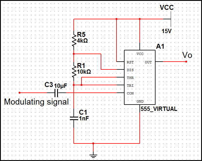
In pulse position modulation, the amplitude and width of the pulses are kept constant, while the position of each pulse with reference to the position of the reference pulse is changed according to the instantaneous sampled value of the...
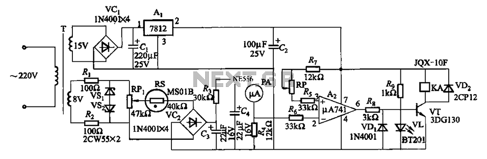
The humidity alarm system is based on integrated circuits and relays, utilizing the pA741 circuit. The MS01 employs a wet-type humidity resistance element as a probe. When the humidity exceeds a predetermined value, specifically set at 6 feet high,...
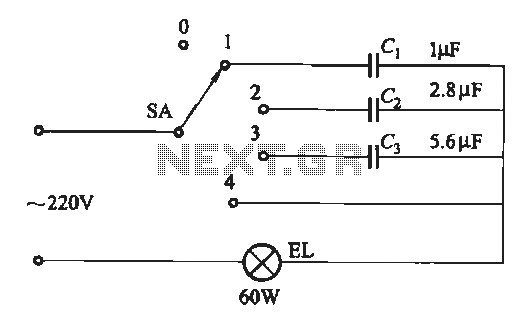
A dimming circuit capacitor circuit is illustrated in Figure 2-63. When the switch SA is moved from position "1" to "3," the capacitance increases in ascending order, resulting in the light bulb brightness also increasing correspondingly. When SA is...
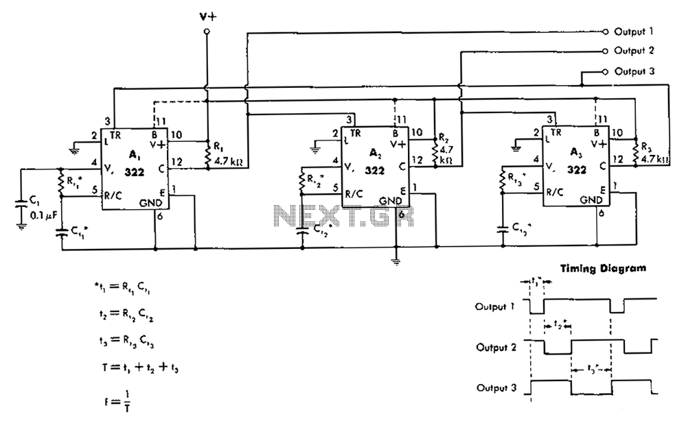
The 322 monostable multivibrator is configured in a cross-connected manner. When operating under non-steady state conditions with the oscillator Unicom, it generates a continuous timing cycle, as illustrated in the accompanying figure. T represents the total time period of...
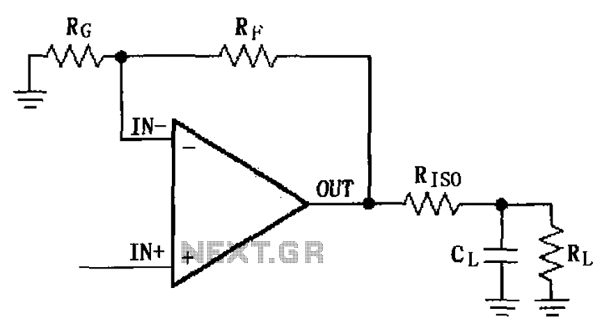
The MAX4223 to MAX4228 series incorporates a capacitive load drive circuit with an isolation resistor (RISO). The maximum allowable capacitive load for these devices is 25pF. However, exceeding this limit can lead to overshoot and ringing. The circuit design...

This liquid detector circuit diagram is designed using common electronic components. The liquid detector can activate an active buzzer to produce sound when a certain water level is reached. Since the water sensor and control circuit for the buzzer...