
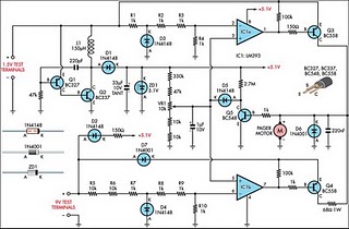
Circuit Diagram Of Motor Control Unit Based On The LM317 IC

The motor control unit circuit utilizes the LM317 voltage regulator to provide a stable output voltage for driving a motor. The LM317 is known for its adjustable output voltage, which can be set using two external resistors. In this configuration, the output voltage can be varied according to the requirements of the motor being controlled.
The circuit typically includes input and output capacitors to ensure stability and reduce noise. The input capacitor helps filter any high-frequency noise from the power supply, while the output capacitor stabilizes the output voltage. Additionally, the inclusion of diodes serves a critical function in protecting the LM317 from voltage spikes that can occur when the motor is switched off or during reverse polarity situations.
In the schematic, the motor is connected to the output of the LM317, and a potentiometer may be used to adjust the resistance, allowing for fine-tuning of the motor speed. The diodes are placed in parallel with the motor terminals, oriented to allow current to flow back into the circuit during the motor's off state, effectively protecting the LM317 from back EMF (electromotive force) generated by the motor.
Overall, this motor control unit circuit provides a reliable solution for controlling motor speed while ensuring the longevity and reliability of the LM317 voltage regulator through adequate protection mechanisms.The following circuit show about Circuit Diagram Of Motor Control Unit. This circuit based on the LM317 IC. Features:diodes protect the regulator, .. 🔗 External reference
Related Circuits
Improved Vibrating Battery Tester. This circuit is based on the LM393 integrated circuit. Features include the ability to test AAA, AA, C, and D cells. The Improved Vibrating Battery Tester utilizes the LM393, a dual comparator IC, to accurately assess...
Generating long delays of several hours can be achieved using a low-frequency oscillator and a binary counter. A single Schmitt Trigger inverter stage (1/6 of 74HC14) functions as a square wave oscillator, producing a low frequency of approximately 0.5...
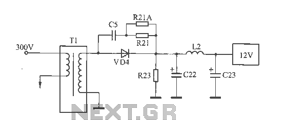
The 12V voltage instability should first be investigated by checking the output section of the switching power supply, as illustrated in the accompanying figure. The secondary winding of the transformer and the switch VD4 have been examined and found...
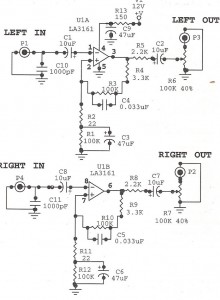
Preamplifiers are utilized to amplify low-level signals, such as those from microphones and tape heads, before they are sent to power amplifiers. Power amplifiers typically exhibit lower sensitivity. The frequency response can also be adjusted and optimized at the...
The circuit is designed to be powered directly by a power supply, which is why it does not include a transformer, rectifier, or filter capacitors in the schematic. However, these components can be added if desired. To operate the...
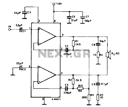
The schematic illustrates a 12 W Bridge Amplifier circuit diagram utilizing the TDA2007A, a class AB dual audio power amplifier. This amplifier is specifically designed for stereo applications in music centers, television receivers, and portable radios. As stated in...