
Circuit Diagram Of Power Amplifier Electronic Circuits

The power amplifier circuit utilizing the LM324 operational amplifier is designed to enhance audio signals for various applications, including RF amplification in audio systems. The LM324 is a quad op-amp, which allows for multiple amplification stages within a single package, making it a cost-effective solution for audio amplification.
In this circuit, the LM324 is configured in a non-inverting amplifier mode to achieve high gain while maintaining a low distortion level. The input signal is fed into one of the op-amps, where it is amplified according to the gain set by the feedback resistors. The output stage of the LM324 can drive loads directly, but for higher power applications, additional transistor stages may be employed to boost the output current capacity.
The circuit also includes coupling capacitors at the input and output to block any DC components, ensuring that only the AC audio signal is amplified. Bypass capacitors are used to stabilize the power supply and reduce noise, which is crucial in maintaining audio fidelity.
Overall, this power amplifier circuit is suitable for applications requiring tube-like audio characteristics, providing a warm sound quality that is often preferred in high-fidelity audio systems. Proper heat dissipation measures should also be considered in the final design to ensure reliable operation during extended use.The following circuit shows about Power Amplifier Electronic Circuits-Tube Audio RF Amplifiers Circuit Diagram. This circuit based on the LM324 IC .. 🔗 External reference
Related Circuits
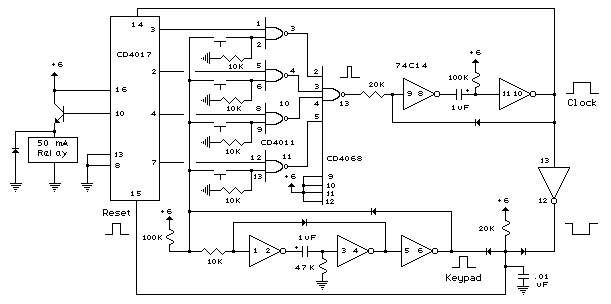
The digital lock shown below uses 4 common logic ICs to allow controlling a relay by entering a 4 digit number on a keypad. The first 4 outputs from the CD4017 decade counter (pins 3,2,4,7) are gated together with...
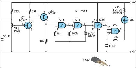
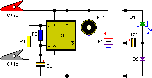
This design integrates power-on and low-battery indications, capable of operating with any battery voltage up to 15V. It features a very low current drain of 2mA or less and costs less than $3.50 with new components. When the battery...
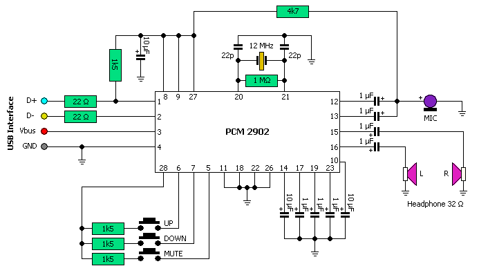
This USB circuit utilizes an integrated circuit (IC) to convert digital voice data into an analog format, making it suitable for headphone use. Additionally, the output can be amplified through a power amplifier, allowing the sound to be played...

Laser Diode Power Supply. This power supply is designed to provide electricity to consumers at low voltage, specifically 220V. While an external adapter can be utilized, it is not recommended due to size constraints. Therefore, a power supply integrated...
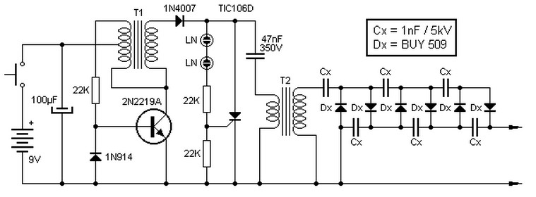
This high voltage source consists of an inverter built around a transistor that generates pulses of 150V. These pulses are supplied to an inverter made of a thyristor and a capacitor, which is connected in series with transformer T2....
This circuit emits an intermittent beep or flashes an LED when the water level in a container reaches a predetermined height. It is designed to be mounted on top of the container, such as a plastic tank, using two...