
Digital Electronic Lock

The digital lock circuit utilizes a combination of a keypad and a CD4017 decade counter to implement a secure access control system. The keypad consists of a matrix of keys, each corresponding to a specific digit. When a key is pressed, it sends a signal to the inputs of the CD4017, which serves as a counter that advances with each correct input. The CD4017 has ten outputs, but only the first four (pins 3, 2, 4, and 7) are utilized in this application to correspond to the four-digit password.
The logic is further controlled by a dual NAND gate, which is responsible for detecting the correct sequence of key presses. Each correct key press produces a low signal at the output of the NAND gate, which is then fed into an 8-input NAND gate. The output of this gate, located at pin 13, transitions to a high state when the correct sequence of inputs is received. This high signal is momentary and is used to trigger a one-shot circuit.
The one-shot circuit is designed to generate a short pulse, which can be used to activate a relay or another output device. In this case, the one-shot circuit is configured to produce a pulse of approximately 80 milliseconds, sufficient to engage a relay that can control a lock mechanism or other electronic devices. This setup ensures that only the correct sequence of key presses will activate the relay, providing a reliable means of access control.
Overall, this digital lock circuit exemplifies a straightforward yet effective method of securing access through electronic means, leveraging common logic ICs to achieve the desired functionality.The digital lock shown below uses 4 common logic ICs to allow controlling a relay by entering a 4 digit number on a keypad. The first 4 outputs from the CD4017 decade counter (pins 3,2,4,7) are gated together with 4 digits from a keypad so that as the keys are depressed in the correct order, the counter will advance.
As each correct key is pressed, a low level appears at the output of the dual NAND gate producing a high level at the output of the 8 input NAND at pin 13. The momentary high level from pin 13 activates a one shot circuit which applies an approximate 80 m 🔗 External reference
Related Circuits
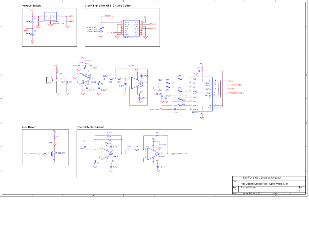
The objective of this project is to design and construct a full-duplex digital fiber optic voice link over a distance of 50 meters with a minimum data rate of 64 kbps. The key components of this project are the...
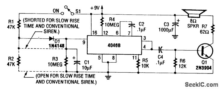
For a normal wailing tone, short D1 and leave R2 open. To achieve a fast rise and slow fall in frequency, include both D1 and R2. Utilizing a CD4046B with a diode-RC network as illustrated generates a siren tone...
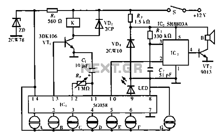
The circuit operates using an ASIC lock IC, specifically the 5C058. Pins 1 to 6 are connected outside the key switch to the positive power supply, representing six valid key inputs. To unlock, keys A through F must be...
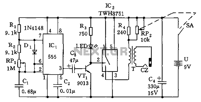
The circuit is composed of a 555 oscillator and an amplifier driver stage. It includes the 555 timer along with resistors R1, R2, RP1, capacitor C1, and other components forming a multi-harmonic oscillator. The frequency can be adjusted using...
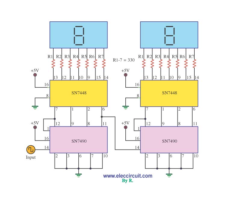
A decade counter circuit is an electronic circuit designed to perform a sequence of numerical calculations, allowing for either forward or backward counting. Forward counting refers to the circuit counting from smaller to larger numbers, while backward counting is...
The following circuit presents a Bell Ring Generator Electronic Circuit Diagram. Features include the generation of a dual-tone bell ringing, similar to most standard bell systems. The Bell Ring Generator circuit is designed to produce a dual-tone output that mimics...