
circuit diagram of remote control tester

The infrared remote control tester circuit utilizes the TSOP1738 infrared receiver module, which is designed to detect infrared signals emitted by remote controls. The circuit operates on a simple principle: when a remote control button is pressed, it emits an infrared signal that the TSOP1738 detects.
The TSOP1738 module is connected to a power supply, typically 5V, and its output pin is connected to a piezo buzzer. In the idle state, the output of the TSOP1738 remains high, meaning that the buzzer remains silent. When the remote control sends a signal, the TSOP1738's output transitions to a low state. This change triggers the piezo buzzer, producing an audible sound that indicates the successful reception of the infrared signal.
The circuit's sensitivity allows it to operate effectively within a range of about 5 meters, making it suitable for testing various remote controls in typical household or office environments. The simplicity of the design ensures that it can be assembled with minimal components, making it a cost-effective solution for users needing to verify the functionality of remote controls.
In addition to the TSOP1738 infrared receiver and the piezo buzzer, the circuit may include basic passive components such as resistors and capacitors to stabilize the power supply and improve performance. Proper placement of these components is essential for achieving optimal sensitivity and reliability. Overall, this infrared remote control tester circuit serves as a practical tool for troubleshooting and verifying remote control devices.An infrared remote control tester circuit that can be made without spenting much money. This IR tester build around an infrared reciever module TSOP1738. We can observe the remote control state by listening to the buzzer sound. The circuit is very sensitive and it support a range of about 5 meters. The infrared receiver module normally rema ins high and the piezo buzzer is in silent mode. When the IR module receives a signal from the remote control, Its output goes low and the piezo buzzer sounds. 🔗 External reference
Related Circuits
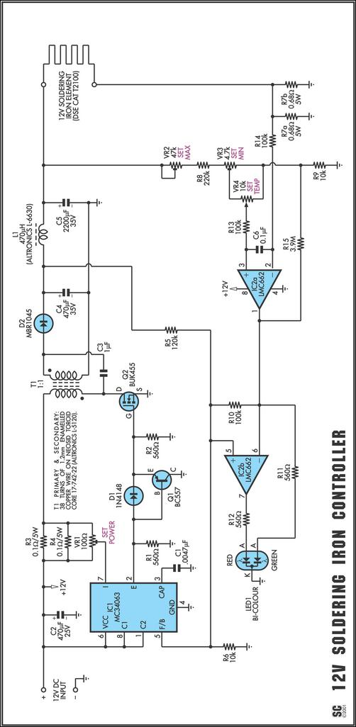
One reason commercial soldering stations are costly is that they typically use soldering irons equipped with built-in temperature sensors, like thermocouples. This circuit design eliminates the necessity for a specialized sensor by directly sensing the temperature of a soldering...
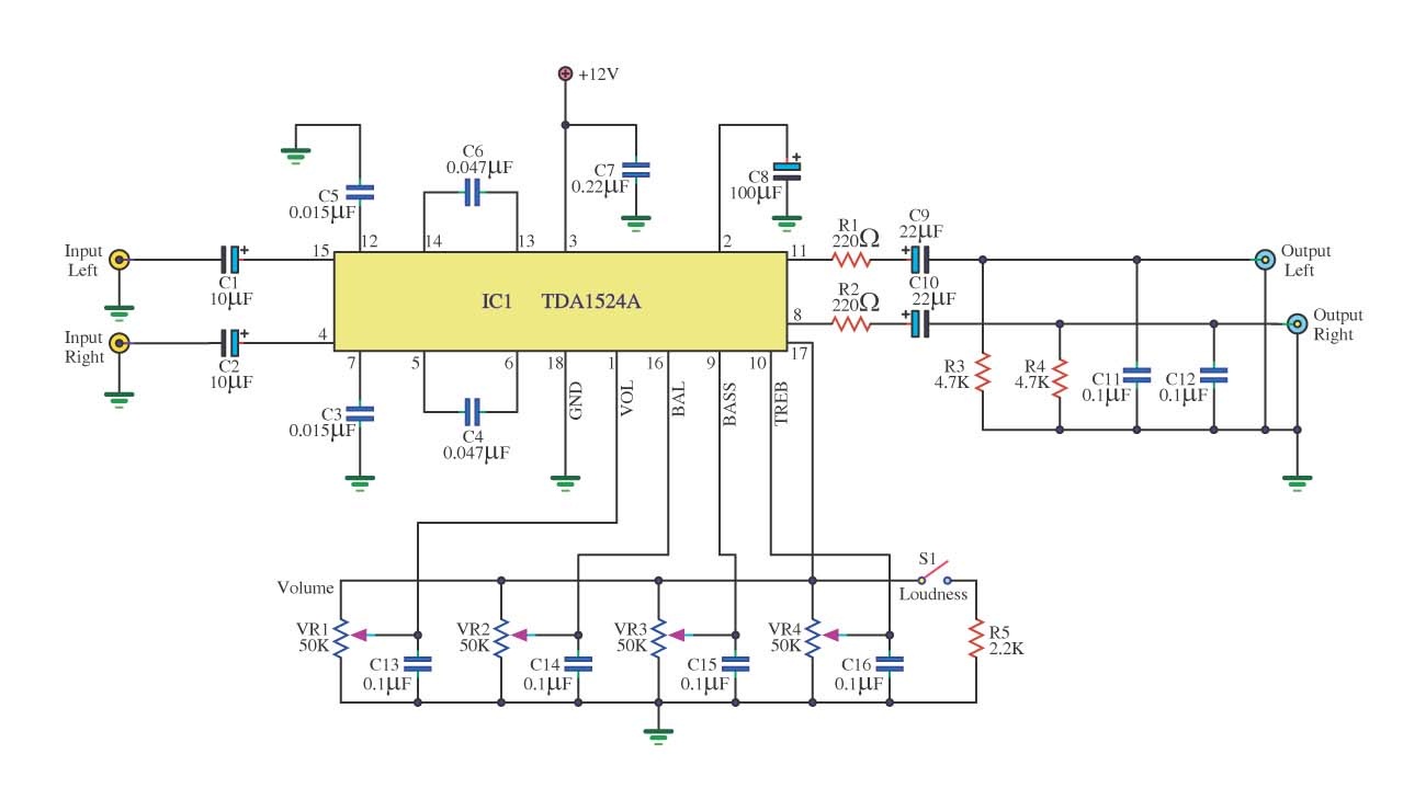
This is a simple tone control circuit using the TDA1524A, which is a key component in this IC chip diagram from Philips. The circuit allows for tone control adjustments such as bass, treble, and balance, enabling users to fine-tune...
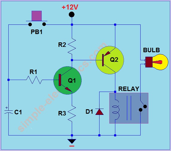
This circuit operates by activating a headlight when the push-button PB1 is pressed. The headlight remains illuminated for a predetermined duration, which can range from several seconds to minutes, before automatically turning off. When PB1 is engaged, capacitor C1...
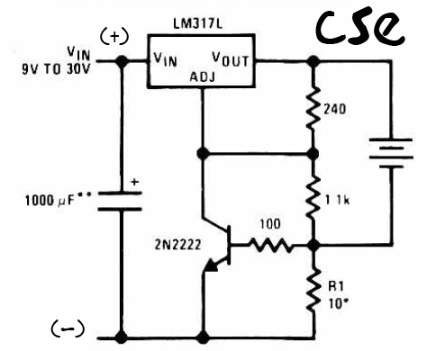
This is a straightforward charger designed for 9V to 30V batteries, primarily operated by the IC LM317L and a 2N222 transistor. It utilizes direct input DC voltage, and a recommended capacitor of 1000µF is included for filtering the output...
This circuit demonstrates a dynamic AC signal level display drive, which can be utilized for audio level display purposes. The AC signal detection and drive control are achieved using the BA6124 integrated circuit, along with five external colored light-emitting...
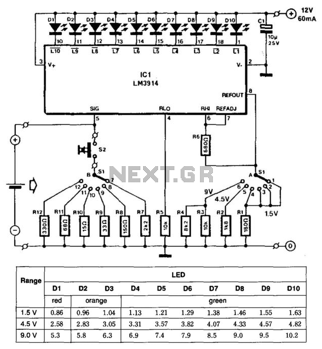
This battery tester utilizes an LM3914 bar-graph driver integrated circuit (IC). Switch SI selects the load on the battery being tested and programs the voltage range. Switch S2 applies the load to the battery under test. A table provides...