
Car Headlight with Delay Circuit

The circuit consists of a push-button switch (PB1), which serves as the primary control element. Upon pressing the button, the circuit is energized, allowing current to flow and charge the capacitor (C1). The charging of C1 is critical, as it determines the time the headlight remains on. The transistors (Q1 and Q2) are configured in such a way that they amplify the current flowing through the circuit, ensuring that the bulb receives sufficient power to illuminate brightly.
Resistors R1 and R3 play an essential role in controlling the discharge rate of the capacitor. The values of these resistors can be adjusted to modify the time it takes for the capacitor to discharge and subsequently turn off the transistors. The relationship between the capacitance of C1 and the resistance values of R1 and R3 can be described by the time constant formula (τ = R × C), where τ represents the time it takes for the voltage to drop to approximately 37% of its initial value. By selecting appropriate values for R1, R3, and C1, the circuit can be fine-tuned to achieve the desired delay duration.
In practical applications, this circuit can be utilized in automotive lighting systems, providing convenience by allowing headlights to remain on for a short period after exiting the vehicle. It enhances safety by ensuring that the area around the vehicle is illuminated, which can prevent accidents in low-light conditions. Additionally, the simplicity of the design makes it suitable for various other applications where a timed delay is required. The circuit's reliability and efficiency can be further improved by selecting high-quality components and ensuring proper thermal management for the transistors.What this circuit does is when you push thepush-buttonPB1, it will make your headlight turns on for several seconds or minutes then it will turn off. The idea of this is when you push PB1, the capacitor C1 will charge and transistors Q1 and Q2 are on.
During this instant, the bulb is on. When PB1 is open, the charge will drain to the resistors R1 and R3 until the capacitor voltage drops to a certain voltage that will turn off the transistor Q1 (bulb is off). Increasing the value of capacitance increases the duration of the delay. The circuit is very similar to Delay Switch using Transistor and Delay Off Circuit. 🔗 External reference
Related Circuits
The circuit of automatic emergency light presented here has the following features: 1. When the mains supply (230V AC) is available, it charges a 12V battery up to 13.5V and then the battery is disconnected from the charging section....
A small (2 to 3 meters) neon electronic transformer circuit diagram is provided below. The described circuit diagram is intended for use with neon lighting systems, specifically those requiring a transformer to operate efficiently within a range of 2 to...
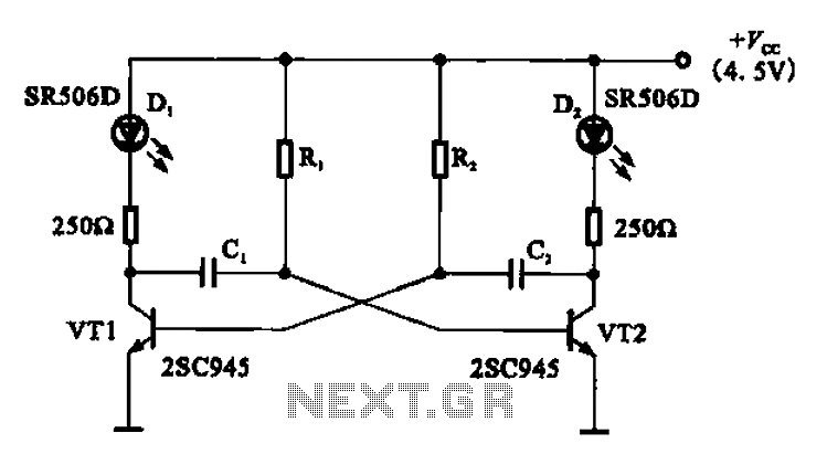
The multivibrator flashing light emitting diode (LED) display driver circuit can be utilized in toys, creating flashing effects in the eyes of animals or monsters. This circuit employs a multivibrator configuration, typically a 555 timer IC or a similar component,...
Incremental rotation or linear encoders are widely used, but they typically do not provide a direction signal. This design presents a straightforward method to detect forward or reverse direction. Incremental encoders usually generate two output signals, referred to as...
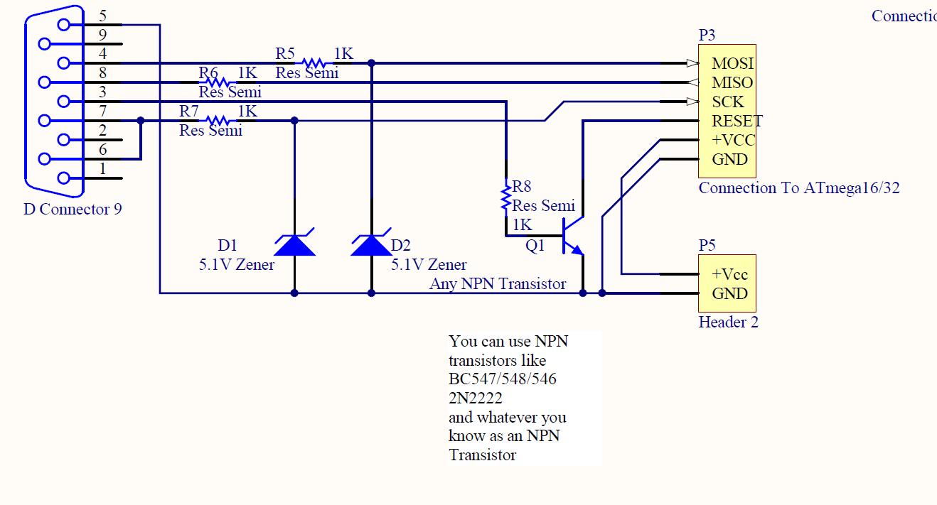
ISP programmer with circuit diagram for AVR Atmega32 microcontroller. This ISP burner circuit is an adaptation of the Pony programmer and uses PonyProg software. The ISP (In-System Programming) programmer designed for the AVR Atmega32 microcontroller facilitates the programming of the...
Just point this small device at the TV and the remote gets jammed. The circuit is self-explanatory. 555 is wired as an astable multivibrator for a frequency of nearly 38 kHz. This is the frequency at which most of...