
Circuit Diagram Of Wii ߀?Sensor߀ Bar Project

The Wii Sensor Bar is a crucial component for the Wii gaming console, utilizing infrared (IR) technology to detect the position of the Wii Remote. The circuit is designed to house multiple infrared LEDs, typically arranged in a linear configuration at both ends of the sensor bar, allowing for a wide detection range.
The infrared LEDs operate by emitting light in the infrared spectrum, which is invisible to the naked eye but can be detected by the sensors in the Wii Remote. This setup enables the remote to determine its position relative to the sensor bar, facilitating accurate motion tracking for gameplay.
The circuit diagram includes a power supply circuit that typically consists of a battery pack or a DC power source, ensuring that the LEDs receive the necessary voltage and current for operation. Current-limiting resistors are also included in the design to prevent excess current from damaging the LEDs.
In practical applications, the sensor bar can be mounted above or below the television screen, and the distance between the infrared LEDs and the Wii Remote should be optimized for effective tracking. The overall design of the sensor bar is compact and efficient, allowing for easy integration into home entertainment setups.
This circuit provides an essential functionality for the Wii gaming experience, enabling interactive gameplay by accurately capturing the movements of the player through the use of infrared technology.The following circuit shows about Wii “Sensor†Bar Project Circuit Diagram. Features: bunch of infrared LEDs on the both ends of a bar, IR .. 🔗 External reference
Related Circuits
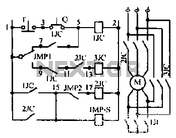
Motor windings are set to connect in a Y configuration while the load is active. The system includes an electric suction mechanism, and the motor is designed to operate under specific conditions. It is rated for 600 revolutions per...

This circuit features open and closed loop contacts (switches 1, 2, 3) that activate the alarm, which remains on for a duration of 5 to 10 minutes. The triggering delay for entrance and exit is set to 27 seconds....
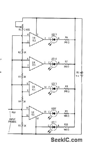
Sections of the RS339 quad comparator each drive an LED to indicate four different input voltage levels. LED 1 is connected to ground to serve as a zero indicator. The resistors depicted are intended for Radio Shack 276-041 red...

Cosmic ray detection can be viewed as an accessible introduction to particle physics experiments. The process of constructing, experimenting, and interpreting results has provided insights into the fascinating particles and forces that constitute the universe. Although documentation of all...

The objective of this project was to create a custom device utilizing local manufacturing resources. At that time, there was a pressing need for a Dub Siren. A circuit diagram was located, and with the assistance of an electronics...

The LM331 is a single voltage-to-frequency conversion integrated circuit (IC) that includes a 1.9 V reference voltage, a current switch, a comparator, and a flip-flop. To expand its operational range, an A1 operational amplifier is added to the circuit....