
frequency conversion circuit composed of LM331

The LM331 is designed for applications requiring precise voltage-to-frequency conversion, making it suitable for use in frequency modulation and digital signal processing. The integration of a 1.9 V reference voltage allows for stable operation across various conditions. The current switch feature enables the IC to toggle output states based on the input frequency, while the comparator function facilitates the comparison of input signals to generate output signals that reflect the frequency of the input.
The addition of an operational amplifier (A1) enhances the circuit's performance by improving the input impedance and allowing for better signal conditioning. This is particularly important when interfacing with sensors or other low-level signals. The reference current (IR) is a critical parameter that influences the frequency output of the LM331. By adjusting the resistors Rl and R(RPl), the designer can finely tune the reference current to meet specific application requirements, ensuring that the output frequency accurately represents the input voltage.
In a typical application, the LM331 can be configured to convert a varying input voltage into a corresponding frequency output. This frequency output can then be used for further processing, such as in frequency counters or digital displays. The design considerations must include the selection of appropriate resistor values to set the desired reference current and the operational amplifier's characteristics to maintain signal integrity throughout the circuit.LM331 is the single voltage / frequency conversion IC within 1.9 v reference voltage, current switch, comparator and flip-flop, etc. In order to expand the range, the circuit is added A1 op amp. The reference current IR is decided by (Rl + R (RPl)), as the internal reference voltage is 1.9 V, IR = l · 9V / (Rl + R (RPl)), the usual range is 100 to 500?A.
I.. 🔗 External reference
Related Circuits
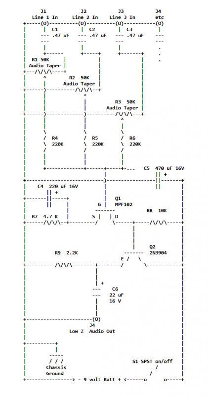
If two of these circuits are made in the same enclosure for stereo, then there can be a single power supply to run both of them. There should be a resistor in series with the incoming 9V+ lead so...
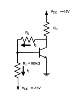
A circuit diagram has been provided for analysis, with the objective of calculating the values of resistors R2 and RC. The circuit is designed to operate at the Q-point with the following parameters: VCE = 5V, VBE = 0.7V,...
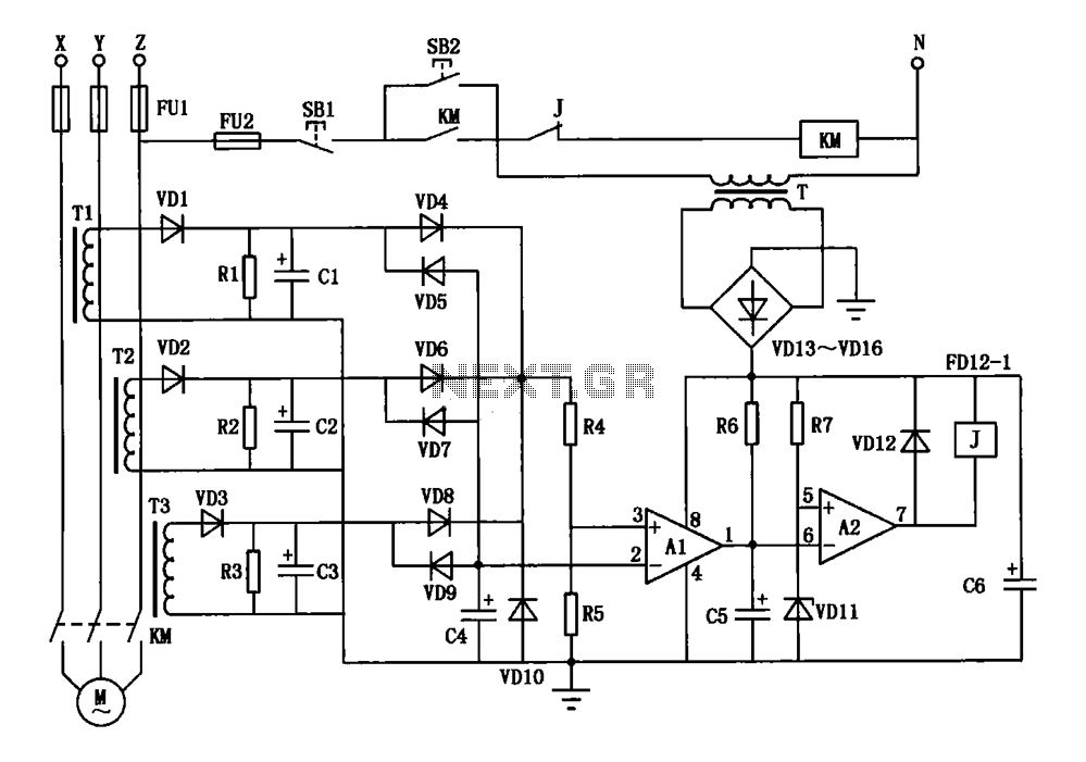
A current three-phase motor phase protection circuit is designed to detect three-phase current using homemade small current transformers T1, T2, and T3. The current signals are collected by rectifiers VD1, VD2, and VD3, while capacitors C1, C2, and C3...
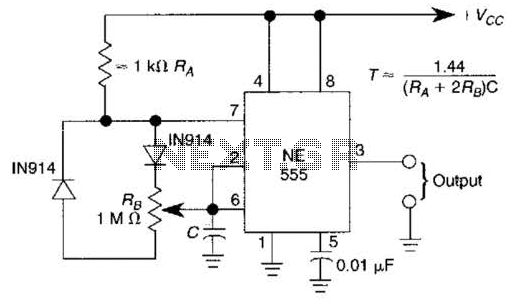
A 1.2-kHz oscillator utilizing a potentiometer and steering diodes allows for a duty cycle adjustment ranging from 1% to 99%. The frequency can be altered by varying the capacitor CI. It is important to note that the diodes may...
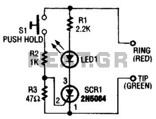
Section Ul-a is configured as a high-gain inverting voltage amplifier that is inductively coupled to the phone line via LI. Inductor LI is a homemade unit that consists of 250 turns of fine, enamel-coated wire that is wound on...
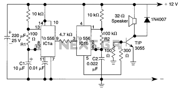
This circuit utilizes a 556 timer IC to initially generate a low-frequency square wave, which is then modulated to produce two alternating tones of approximately 400 Hz and 500 Hz. The circuit is designed to create a warble alarm...