
Circuit Egg Timer By LM555
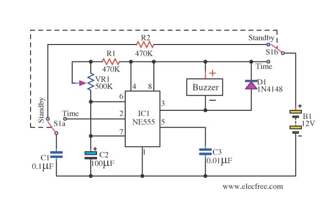
The circuit utilizes the popular 555 timer integrated circuit (IC) in astable mode to create a timing function. The configuration allows the user to set a specific time interval during which the circuit operates. The heart of the circuit includes the 555 timer, resistors, capacitors, and a buzzer.
In this design, the timing interval is determined by the values of the resistors (R1, R2) and the capacitor (C1). The output from the 555 timer is connected to a buzzer, which serves as the alarm indicator. When the timer reaches the set interval, the output goes high, activating the buzzer. The circuit can be powered by a standard DC power supply, typically in the range of 5-15V, making it suitable for various applications.
To enhance usability, a potentiometer can be included in the circuit to allow for adjustable timing. The addition of a reset button can also be beneficial, enabling the user to stop the timing process at any point. The overall design is compact and can be easily housed in a small enclosure, making it convenient for portable applications.
This Egg Timer circuit is ideal for cooking, where precise timing is essential, and can be adapted for various other timing applications as needed. The straightforward nature of the circuit makes it an excellent project for beginners in electronics, providing practical experience with the 555 timer IC and basic circuit design principles.This is Easy and Mini Timer Circuit ( Egg Timer) by IC 555. Alarm by Buzzer. This be mini timer circuit that interesting. I calls that Circuit Egg Timer. By. 🔗 External reference
Related Circuits
The most extreme option would be to supply power through a battery pack. A more plausible source would be the car's battery. However, since the objective of the circuit is to activate the buzzer when the headlights are on,...

A Field Effect Transistor (FET) is an amplifying device where the output current is influenced by the input voltage. The FET preamplifier described here is sensitive. The Field Effect Transistor (FET) operates by utilizing an electric field to control the...
This circuit controls a small, four-phase, five-wire, unipolar stepper motor, commonly designated as the "KP4M4-001." This type of motor was utilized in many 5 1/4" floppy disk drives in older computers. Although now obsolete, such disk drives are often...
A 12-volt power supply is used to operate a sequencer board that controls external relays for coaxial relays, a preamplifier, and an amplifier. The sequencer board features DIL relays designed to drive these external relays. Although there are more...
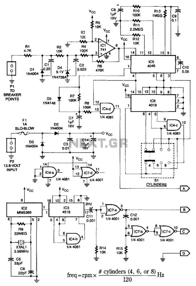
This system is compatible with 4-, 6-, or 8-cylinder automobiles. The timebase generated by IC5 functions as an oscillator that drives counter IC6, which divides the frequency by 6, 4, or 3 for 4-, 6-, or 8-cylinder engines, respectively....
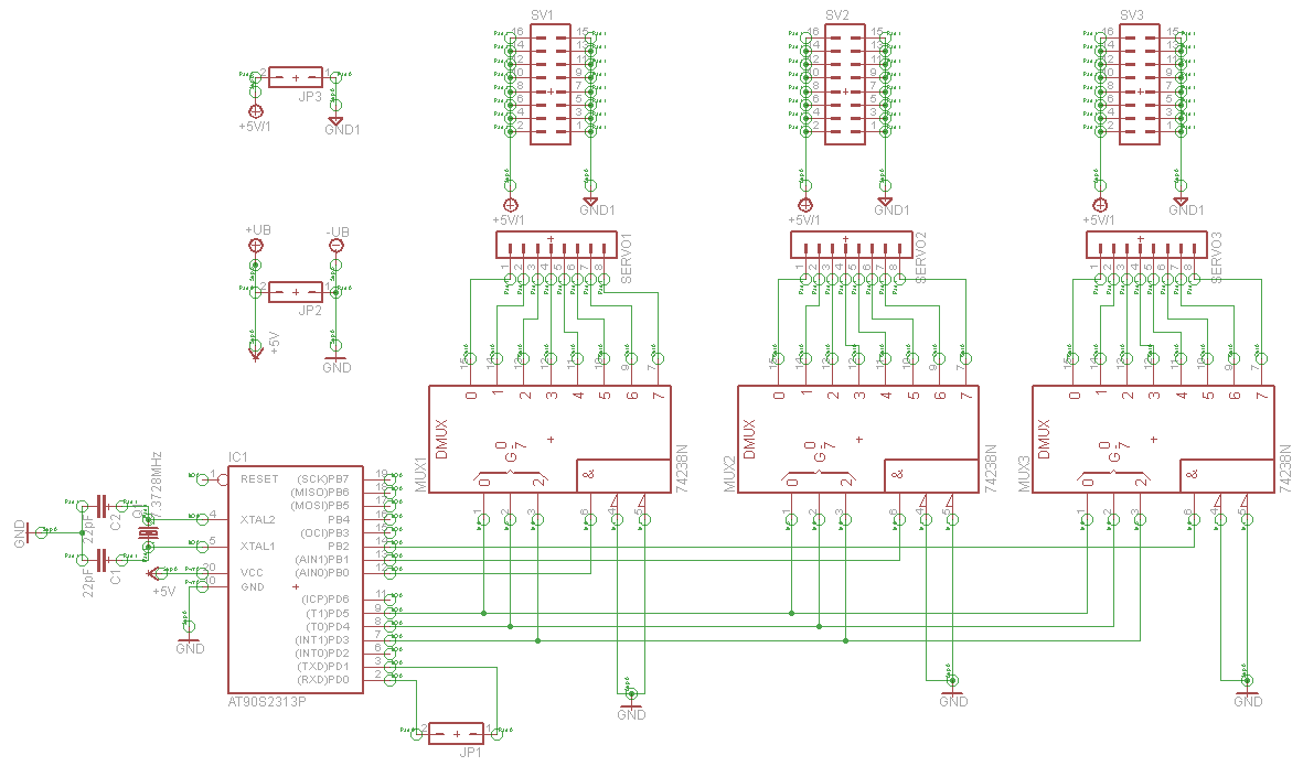
A serial servo controller is being developed to enhance knowledge of electronics and assembly language as part of a hexapod robot project. Initially, the ATTiny2313 microcontroller was utilized; however, it became evident that additional I/O channels were necessary. Consequently,...