
Digital Tachometer Circuitry

This system is designed to operate with various engine configurations, providing flexibility in automotive applications. The oscillator IC5 is crucial for generating a stable timebase, ensuring accurate frequency division for the different engine types. The selection switch S1 allows the user to easily configure the system for the engine in use, enhancing usability.
The phase-locked loop functionality of IC5 ensures that the output signal remains synchronized with the ignition system's frequency, which varies with engine speed. This synchronization is vital for maintaining accurate engine monitoring and performance metrics. The conditioning of the ignition signal by IC1 is essential for proper interfacing with the subsequent circuitry, ensuring that noise and other unwanted signals are minimized.
The output from IC4D is critical as it provides a frequency that is directly related to the engine's operational parameters. This frequency is then displayed in real-time, allowing for immediate feedback on engine performance. The generation of a 60-Hz signal by IC2, derived from a 3.58-MHz reference, showcases the use of frequency synthesis techniques to produce standard timing signals.
The division of the 60-Hz signal by IC3 and IC4B to achieve a 2 Hz output demonstrates the system's capability to generate lower frequency signals suitable for various timing applications within the circuit. The delayed 2-Hz signal produced by the combination of IC7B, IC7C, C12, and R15 adds a layer of functionality, allowing for time-based operations such as counting or triggering events within the system.
Overall, this electronic schematic represents a sophisticated approach to engine monitoring and control, utilizing phase-locked loops, frequency division, and signal conditioning to achieve reliable and accurate performance metrics for automotive applications. This system can be used with 4-, 6-, or 8-cylinder automobiles. The timebase formed by IC5 is an oscillator th at drives counter IC6, which divides by 6, 4, or 3 for 4-, 6-, or 8-cylinder engines, respectively. S1 selects this number. IC5 produces a signal that is phaselocked to this multiple of the ignition system frequency, which in turn depends on engine speed. IC1 conditions the ignition input at PI to feed ICS. The output of IC4D, which is the same frequency as the VCO in ICS, is fed to the frequency display. IC2 generates a 60-Hz signal using a 3.58-MHz reference. IC3 and IC4B divide this by 30 to produce 2 Hz. IC7B/IC7C and C12/R15 produce a delayed 2-Hz signal. These signals are fed to the counter circuit.
Related Circuits
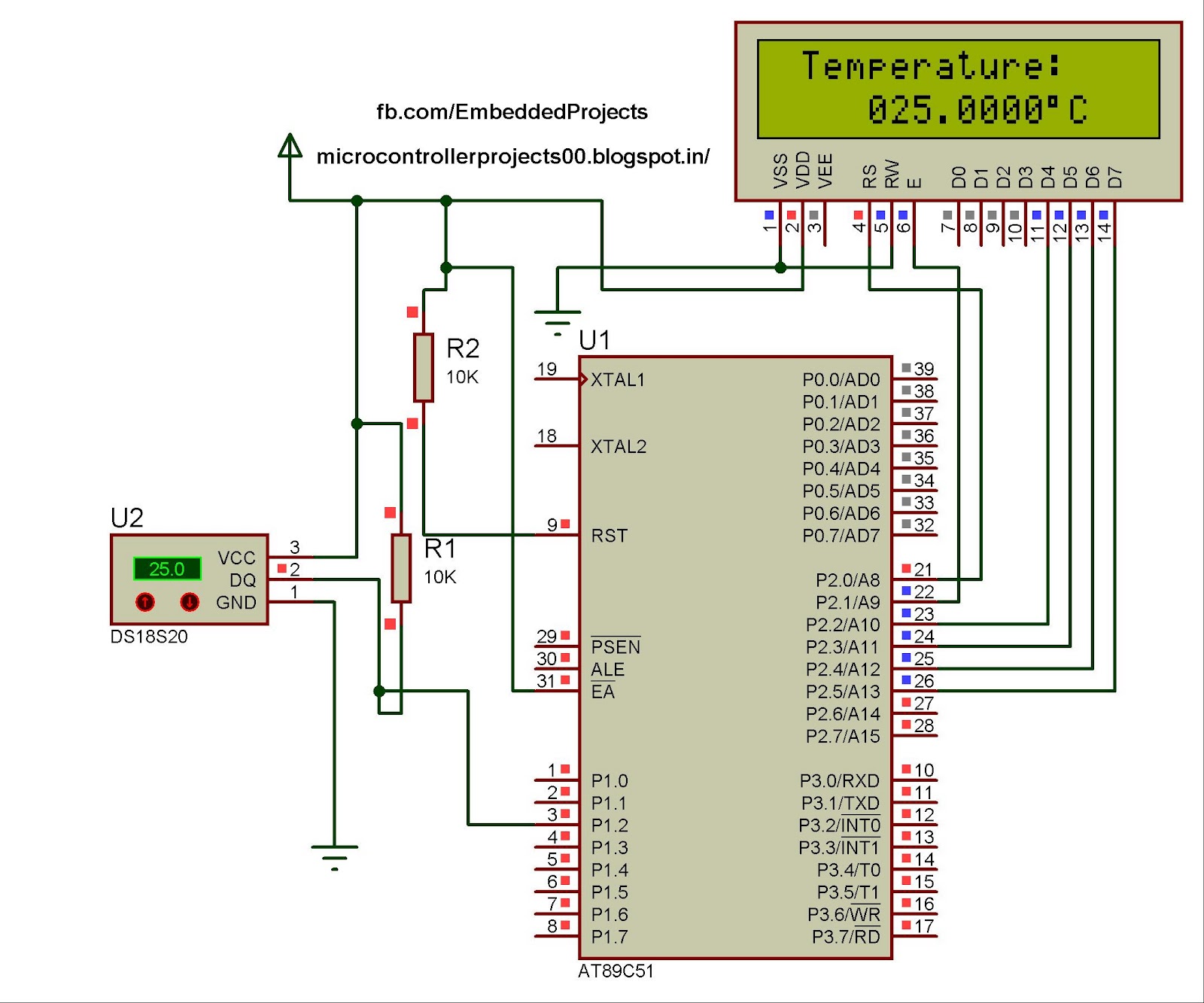
The hardware configuration for utilizing multiple 1-Wire temperature sensors, such as the DS1820, is straightforward. Communication between the microcontroller and the temperature sensors occurs over a single-wire bus, which can also supply power to the devices. An extensive number...
Power the frequency counter and adjust the coarse (top pot) and fine (bottom pot) controls to display zero frequency. Turn the pots counter-clockwise to achieve a zero reading. Occasionally, the counter may show only squares without digits. If this...
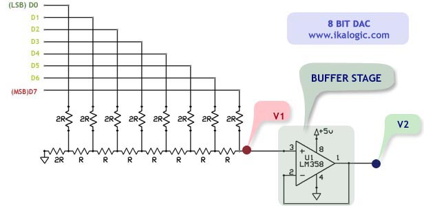
This article introduces a simple solution for beginners and intermediate readers to build a digital-to-analog converter (DAC) using an R/2R resistor network. It also addresses common challenges faced by beginners while constructing their own DACs and offers straightforward solutions....
Security is a prime concern in our day-to-day life. Everyone wants to be as much secure as possible. An access control for doors forms a vital link in a security chain. The microcontroller based digital lock for Doors is...
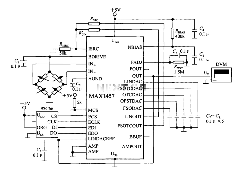
The circuit diagram illustrates a digital precision pressure tester using the MAX1457 integrated circuit with an external ROM selection of the 93C66 type, which is a 4096-bit E2PROM. Upon powering on, the MCS pin is pulled to a high...
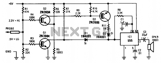
The probe's input circuit detects the signal condition and generates a low-pitched tone for low-level signals (below 0.8 V) or a high-pitched tone for high-level signals (above 2 V). The tone probe employs sound to indicate the status of...