
Circuit for power linear RF amplifier with BLY90

The RF power amplifier circuit is designed to enhance signal strength in high-frequency applications, making it suitable for amateur radio or other RF transmission systems. The choice of a BLY90 transistor is critical due to its ability to handle high frequencies and its robust current handling capabilities. The specified RF chokes play a vital role in suppressing unwanted high-frequency noise, ensuring that the output signal remains clean and within the desired frequency range.
The assembly of the circuit requires attention to detail, particularly in the layout of the PCB to minimize lead lengths, which can introduce parasitic inductance and capacitance that may affect performance. The use of ceramic capacitors is recommended due to their stability and reliability at high frequencies, as opposed to electrolytic capacitors, which may introduce distortion.
The transformer selection is another crucial factor; using an ATX power supply transformer can simplify the design process, as these components are readily available and designed for high efficiency. The RF chokes' inductance values must be verified to ensure they meet the circuit's operational requirements.
Finally, compliance with relevant regulations is essential to ensure that the amplifier does not interfere with other communications systems and operates within legal limits. Proper heat dissipation for the BLY90 is also necessary to prevent thermal failure during operation, necessitating the use of a suitable heatsink. This comprehensive approach to design and assembly will result in a reliable and effective RF power amplifier.It is to be used as amplifier of potency of RF in the high strip of of the power source that should be capable to supply a tension of 13 volts with a current of 10 amperes. it demands right care in the assembly of the source. Terrified armored transformer, and three shocks of RF to filter the components of high frequency. XRF1 and XRF2 are 30 youturns of wire 25 AWG in a nucleus of ferrite of 1 cm of diameter and 5 cm length. It can use one of a source at/atx bad, it is easier. XRF3 are 100 you turns of wire 25 AWG in a ferrite nucleus and 1cm of diameter for 5cm of length. Or use an usually found in the exits of sources ATX`s. something around 100 µH. The capacitors C1, C2, C3, C4 should be ceramic of 600 V or more and the capacitors of 10nF are for 100v. RX cannot be of wire. The Transistor BLY90 was developed to work in the classes THE, B and C, with 12. 5V current of 8A. For applications above 175MHZ. Below we have the diagram circuit of the amplifier using an only transistor BLY90. All capacitors should be ceramic. The resistor of 10 © for 1 w should not be of wire, the entrance impedance and exit is of 50 ©, soon it should be linked with cable of 50 ©.
It should be observed the legal restrictions as the operation of that equipment type. Below we have the drawing of the printed circuit board of the transmitter, observe that the components are mounted beside the copper and with the terminals the shortest possible, use heatsink in BLY90. 🔗 External reference
Related Circuits
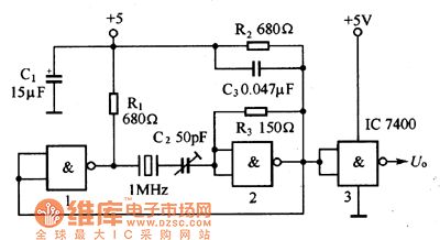
The oscillator circuit consists of a 1MHz quartz crystal resonator and a NAND gate, with the output buffer stage provided by NAND gate 3. This circuit can be utilized for calibrating standard frequency. The described oscillator circuit operates at a...
This innovative buzzer circuit incorporates a relay connected in series with a small audio transformer and a speaker. When the switch is activated, the relay is energized through the primary winding of the transformer and the closed relay contact....

This heatsink temperature monitor circuit uses three LEDs to signal when the temperature exceeds two boundary levels. When the heatsink temperature is below 50 degrees... This heatsink temperature monitor circuit is designed to provide visual indications of temperature levels using...

The control module monitors the fuel tank pressure (FTP) sensor signal to detect vacuum decay and excess vacuum during the enhanced evaporative emission (EVAP) diagnostic. The Fuel Tank Pressure Sensor responds to changes in the fuel tank pressure or...

To design a Tube Headphone Amplifier we need a triode with uncommon characteristics: enough voltage gain, low internal resistance and good anodic current. My first test was done with the E182CC, but there is the limitation on the usable...
This Wien bridge oscillator is straightforward and, like all Wien oscillators, exhibits low distortion. The resonance frequency can be easily adjusted. The Wien bridge oscillator is a type of electronic oscillator that generates sine waves. It is based on the principle...