
Wien Bridge Oscillator Circuit

The Wien bridge oscillator is a type of electronic oscillator that generates sine waves. It is based on the principle of a bridge circuit, which includes resistors and capacitors arranged in a specific configuration. The circuit typically consists of two resistors and two capacitors, configured to form a feedback loop that allows for the generation of oscillations.
The fundamental frequency of oscillation is determined by the values of the resistors and capacitors used in the circuit. By adjusting these component values, the resonance frequency can be altered, allowing for a wide range of output frequencies. This adjustability is a significant advantage, making the Wien bridge oscillator suitable for various applications in audio and signal processing.
To maintain oscillation, the circuit often includes an automatic gain control mechanism. This is typically achieved using a thermistor or a light-dependent resistor (LDR) in the feedback path, which helps stabilize the amplitude of the output signal. As the output amplitude increases, the resistance of the controlling element changes, reducing the gain and preventing distortion.
The output of the Wien bridge oscillator is a clean, sinusoidal waveform, which is advantageous for applications requiring low distortion, such as audio signal generation or testing. The design of the circuit allows for easy implementation on a breadboard or PCB, making it accessible for both educational purposes and practical applications in electronic design.
Overall, the Wien bridge oscillator is a valuable circuit in electronics, known for its simplicity and effectiveness in generating stable sine wave signals.THis Wien bridge oscillator is very simple and as every wien oscillator has low distorsion and the resonance frequency can be easily adjusted. This frequen.. 🔗 External reference
Related Circuits
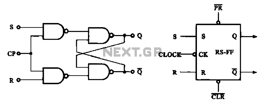
The asynchronous RS flip-flop mentioned earlier is not synchronized with the system clock signal. In contrast, the synchronous RS flip-flop incorporates synchronization, allowing it to operate in conjunction with the clock signal. Figure (a) illustrates the circuit configuration of...
When an alternating current signal is applied to a capacitor, the phase of the charging current and the voltage across the capacitor shifts by 90 degrees. Conversely, when an alternating current signal is applied to an inductor, the voltage...
This circuit is utilized in an impulse speed modulation system. In this system, the transmitter alters the impulse speed of the modulated beam in an optical fiber, allowing it to vary around a center frequency of 50 kHz. The...
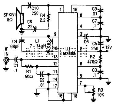
An LM2808 performs IF amplification of the 4.5-MHz sound subcarrier, limiting, detection, and audio amplification. If the center frequency must be changed, then change L1/C4. Audio output is 0.5 W. R3 is the volume control. The LM2808 is an integrated...
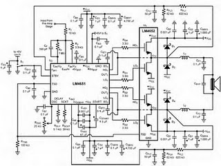
The following circuit illustrates the LM4652 integrated circuit used in a 170 Watt power amplifier configuration. It is commonly utilized in portable HiFi systems. The LM4652 is a high-performance audio amplifier IC designed to deliver substantial power output while maintaining...
Application circuit using three stereo digital potentiometers to control volume, balance, and fader in a four-speaker configuration with a push-button interface. The application circuit utilizes three stereo digital potentiometers, which are essential components for managing audio levels in a multi-speaker...