
Stepper Motor Control Circuit

The described circuit involves a stepper motor control system utilizing two LMD18245 motor driver chips, which are designed to facilitate the precise control of current through the coils of the stepper motor. Each LMD18245 is responsible for one coil, allowing for independent control of each phase of the motor. The LMD18245 is a high-performance, dual H-bridge driver that can handle high current loads, making it suitable for driving stepper motors.
In contrast to using a single driver chip, such as the L298, which can control both coils of a stepper motor, the dual chip configuration provides enhanced control and flexibility. This configuration allows for smoother operation and better torque management, as each coil can be driven with tailored current profiles.
For applications requiring the simultaneous control of two stepper motors, the SN754410 is a viable alternative. This chip is capable of managing two two-coil stepper motors, simplifying the design and reducing the number of components needed in the circuit.
The control of current flow direction is critical in stepper motor applications. By reversing the current through the coils, the motor can be made to step in either direction, allowing for precise positioning and movement. The accompanying code, which will be discussed further, outlines the necessary commands and timing sequences to achieve accurate control of the stepper motor's operation.
In summary, the circuit design utilizing two LMD18245 chips for a two-coil stepper motor provides a robust solution for applications requiring detailed control of motor movement. The choice between single and dual driver chips depends on the specific requirements of the motor control application, including performance, complexity, and the number of motors to be controlled. The source code necessary for implementing this control will be available for download, providing a practical resource for developers and engineers working with stepper motors.This circuit is not fun to look at nor is it fun to implement, it takes a bit of effort. Since there are two coils in our stepper motor we`ll use two LMD18245`s to control the current flow through the coils. It is important to note that there are motor control chips like the L298 that offer stepper motor control u
sing only 1 chip. You can also find chips that have the capability of controlling two of these 2 coil stepper motors at once, the SN754410 for example. Next we`ll see take a look at the code necessary to control the stepper motor and see exactly why control of the current flow direction is so important.
Scroll down to the bottom to download the source code file. 🔗 External reference
Related Circuits
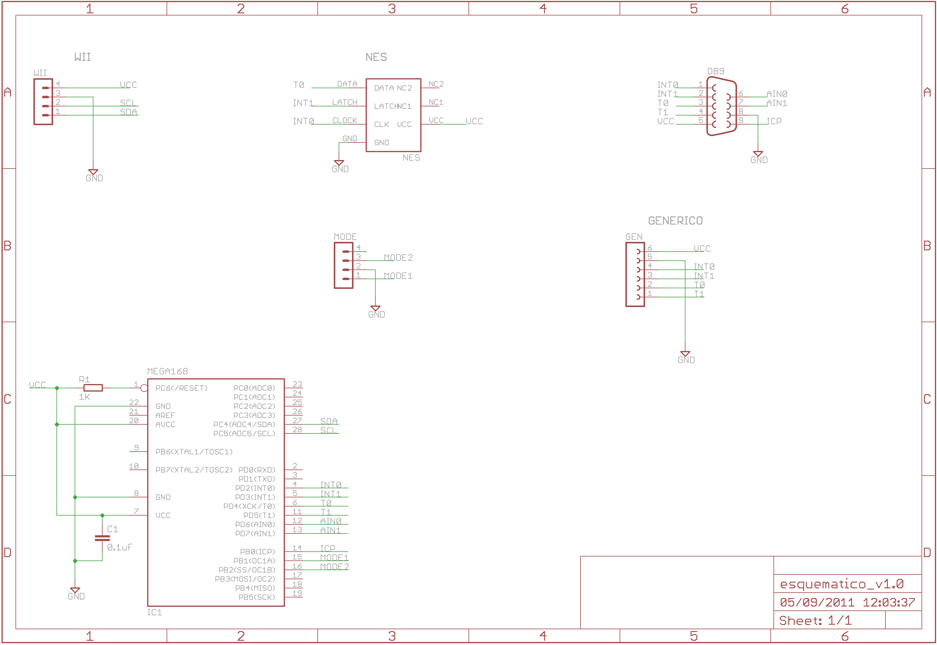
The Wii RetroPad Adapter allows the use of PlayStation 2, Genesis, NES, and SNES controllers with the Wii console. The Wii RetroPad Adapter is a versatile accessory designed to enhance the gaming experience by enabling compatibility between multiple classic gaming...
Here is a handy zener diode tester which tests zener diodes with breakdown voltages extending up to 120 volts. The main advantage of this circuit is that it works with a voltage as low as 6V DC and consumes...
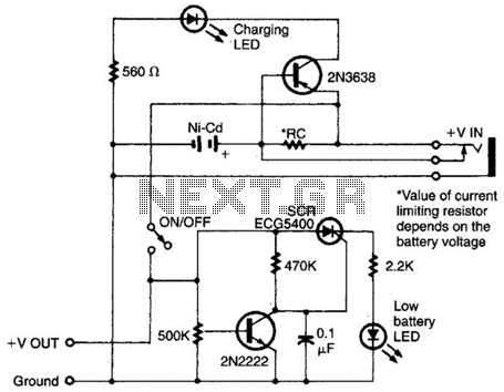
Intended for a NiCad application, this charging circuit can be used with a wide range of batteries. A low-battery detector is included, and the trip voltage is set via a 500 kΩ potentiometer. Select the resistor for the battery...
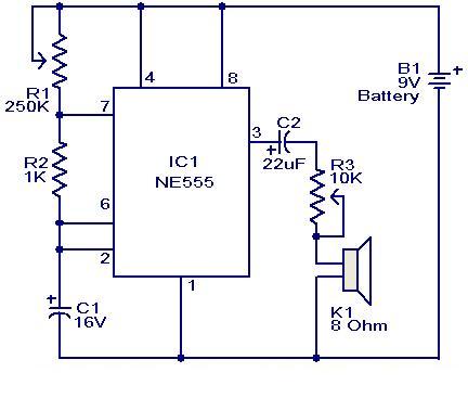
This weblog focuses on electronic circuit schematics, PCB design, DIY kits, and diagrams for electronic projects. A simple circuit utilizing the NE555 IC is presented, which can be employed to generate metronomes. This circuit is particularly beneficial for music...
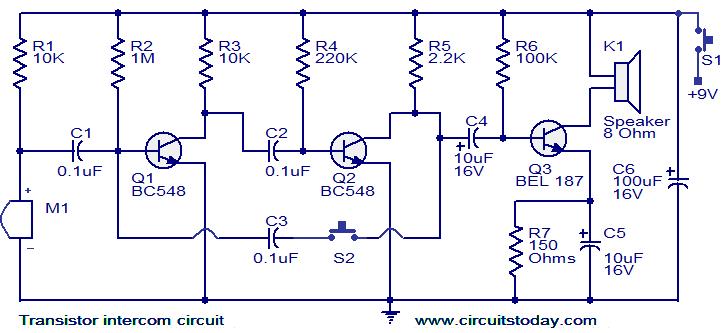
This document describes a simple yet effective intercom circuit that is entirely based on transistors. The design features a three-stage RC coupled amplifier. When the pushbutton S2 is activated, the amplifier circuit, which includes transistors T1 and T2, functions...
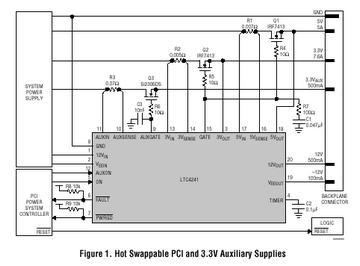
The LTC 4241 is a Hot Swap controller that enables safe insertion and removal of a board from a live PCI-bus slot. It features a primary controller that manages the four PCI supplies, along with an independent auxiliary controller...