
Circuit having a high school bass tone function

The circuit described operates within a defined frequency range, facilitating effective audio processing. The low corner frequency of 30 Hz indicates that the circuit can handle deep bass signals, making it suitable for applications requiring low-frequency response, such as subwoofers or audio systems designed for bass-heavy music genres. The high corner frequency of 1 kHz establishes an upper limit for the circuit's operation, ensuring that it effectively filters out unwanted high-frequency noise while maintaining the integrity of the audio signal within the desired range.
The control range of 20 dB provides significant flexibility in adjusting the bass response, allowing for customization based on user preferences or specific audio environments. The operational amplifier utilized in this circuit is crucial for achieving the desired amplification and tone control, ensuring that the audio signals are processed with minimal distortion and optimal fidelity.
The buffer stage, represented by Ai, plays a vital role in this design by isolating the preamplifier output from the subsequent stages of the circuit. This isolation is essential for preventing loading effects that could degrade the signal quality. By reducing the burden on the preamplifier, the buffer allows for improved overall performance and stability of the audio system.
In summary, the circuit design integrates advanced audio processing capabilities with a focus on low-frequency performance and user control, making it an effective solution for enhancing audio quality in various applications. The schematic in Figure 4-9 provides a visual representation of the circuit, detailing the connections and components involved in achieving the specified functionality.Figure 4-7 pitch analysis using the relation obtained above design calculation control circuit, where Ai is a buffer to put the big stage, to reduce the burden preamp output. L ow-corner frequency of the circuit is 30Hz, high frequency corner frequency of 1kHz, the control range of 20dBo not only to design an operational amplifier having a high bass control tone circuit functions, but also to design a high school bass control tone system function the control circuit, the actual circuit shown in Figure 4-9.
Related Circuits

A 30- to 50-cm whip antenna provides reception from 10 kHz to over 220 MHz. Tl, a dual-gate MOSFET, provides low noise, high-input impedance, and high gain. The circuit is powered via the coaxial cable used to connect the...
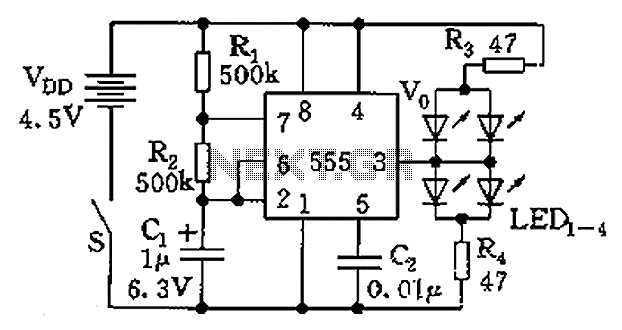
The circuit consists of a 555 timer and a light-emitting diode (LED) array. The 555 timer, along with resistors R1, R2, and capacitor C1, forms an astable multivibrator configuration. The oscillation frequency is calculated using the formula f =...

This car audio amplifier circuit is based on the LA47536 audio amplifier integrated circuit designed by Sanyo. This audio amplifier circuit is specifically designed for car audio power amplifiers. The LA47536 car audio amplifier IC features four output channels...
This is the simplest VU meter that can be constructed. It is based on a single integrated circuit. A volume unit (VU) meter, or standard volume indicator, is a device used to display the level of any voltage signal...
This circuit is designed to indicate when a plant requires watering. An LED flashes at a low frequency when the soil in the flower pot is excessively dry, and it turns off as the moisture level rises. The sensitivity...
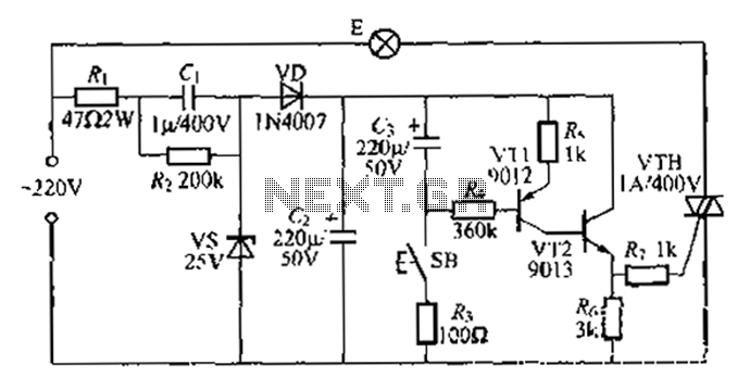
Another method employs a Zhu gall thyristor delay lamp circuit. Typically, a 220V AC supply is used, consisting of a step-down voltage half-wave rectifier circuit. The circuit outputs approximately 25V across the left and right terminals. At this point,...