
Bidirectional thyristor delay lamp circuit 2

The Zhu gall thyristor delay lamp circuit effectively uses a combination of AC to DC conversion, transistor switching, and thyristor control to manage the illumination of a lamp. The design begins with a 220V AC input, which is reduced to a safer 25V through a half-wave rectifier circuit. This reduction is crucial for protecting sensitive components and ensuring safe operation. The two transistors, VT1 and VT2, serve as switches that control the flow of current to the thyristor. When the switch SB is activated, it triggers the base of VT1, allowing current to flow through the circuit and subsequently turning on the transistors.
The role of the capacitor C is significant in this circuit. It charges quickly when the switch is closed, and its stored energy helps maintain the conduction of VT1 even after the switch is opened. This characteristic allows for a gradual dimming effect as the capacitor discharges, providing a smoother transition of light output from the lamp. The circuit design can be fine-tuned by altering the resistance values of R1 and R2, as well as the capacitance of C. This flexibility allows for customization of the delay time, making the circuit suitable for various applications where controlled lighting is desired.
The operation of the circuit can be summarized in the following sequence: Initially, when the lamp is off, the transistors are not conducting, and the thyristor remains inactive. Upon closing the switch, the transistors are activated, allowing current to flow and the lamp to light up. Once the switch is opened, the capacitor C maintains the conduction state of VT1, keeping the lamp dimly lit until the capacitor discharges sufficiently. The gradual reduction in voltage across the resistors leads to a decrease in the thyristor's conduction angle, resulting in the lamp slowly fading out. This circuit design exemplifies a practical application of thyristor technology in lighting control systems.Another method uses Zhu gall thyristor delay lamp circuit. Usually, 220V AC via vr), vs, (,, c: isoelectric consisting of step-down voltage half-wave rectifier circuit, in f st able 25V output ends of the left and right straight. At this time the pressure flow la transistor VT1,. VT2 are in the oFF state, bidirectional thyristor tube trigger current, especially in the off state, F does not light the lamp. lights when needed, then ~ F SB, 25v DC via R., Rj to VT1 Almost bias current fed into the base, V1, l, VT2 have been turned on, vrH get trigger current opened, the lamp is powered E-emitting, meanwhile, (, full charge through rapid blood R.
after releasing the SB, r. stored charge by R. dare to VT1 electric, we are still able to maintain VT1 conduction, small lights will go out. with G continues to discharge, VTI, VT2 conduction to the original zoom into nervous state, and ultimately restore the oFF-state, so R. voltage becomes smaller, eventually reduced to zero, the thyristor conduction angle vrH also will be smaller after the moth becomes zero Wei, E light fades until it goes off.
change R., Gs, uh value to change the delay time of the circuit can be adjusted as needed .
Related Circuits
This page provides basic information about voltage comparator integrated circuits and is to act as reference material for other circuits. The circuits shown are based on the LM339 Quad Voltage Comparator chip or the LM393 Dual Voltage Comparator chip....
A simple square wave oscillator can be created using two gates from a CMOS 4011 NAND chip. Alternatively, a CMOS 4001 chip or a TTL equivalent can also be utilized. In this circuit, the mark-space ratio can be independently...
In this fire alarm circuit, a thermistor functions as the heat sensor. As the temperature rises, its resistance diminishes, and conversely, when the temperature falls, its resistance increases. At standard temperature, the resistance of the thermistor (TH1) is approximately...
The bipolar junction transistor is one of the cornerstones of modern solid-state electronics. Understanding the basics of this important active device is essential. The Bipolar Junction Transistor (BJT) initiated the revolution in solid-state electronics during the 1960s. Although discrete...
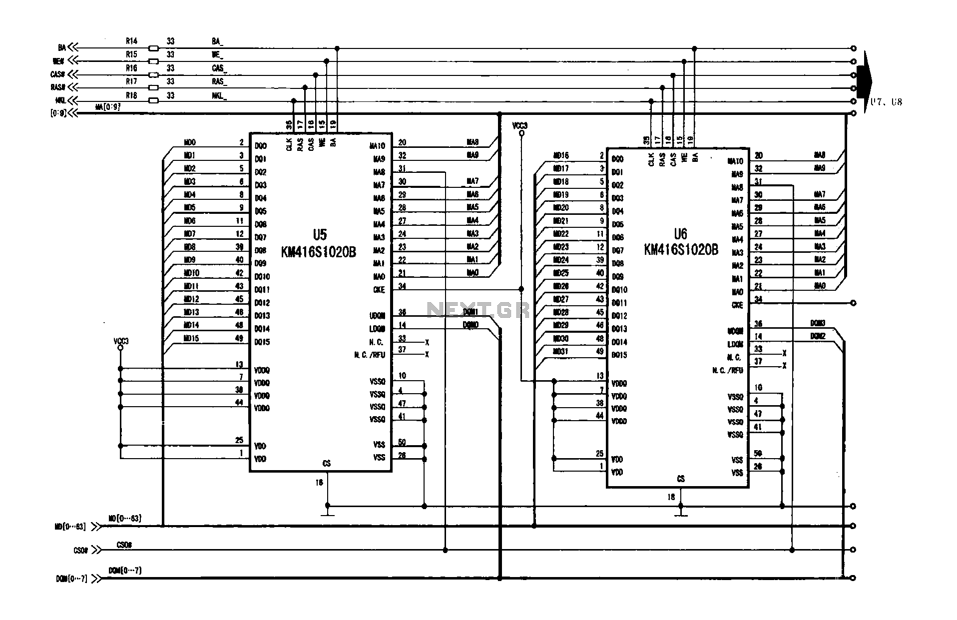
A digital signal processing circuit that operates in conjunction with a memory system for temporarily storing image data. The DPTVT-3D/MV digital processing chip requires four KM416S102 memory units, each providing 16 MB of digital memory. The circuit structure is...
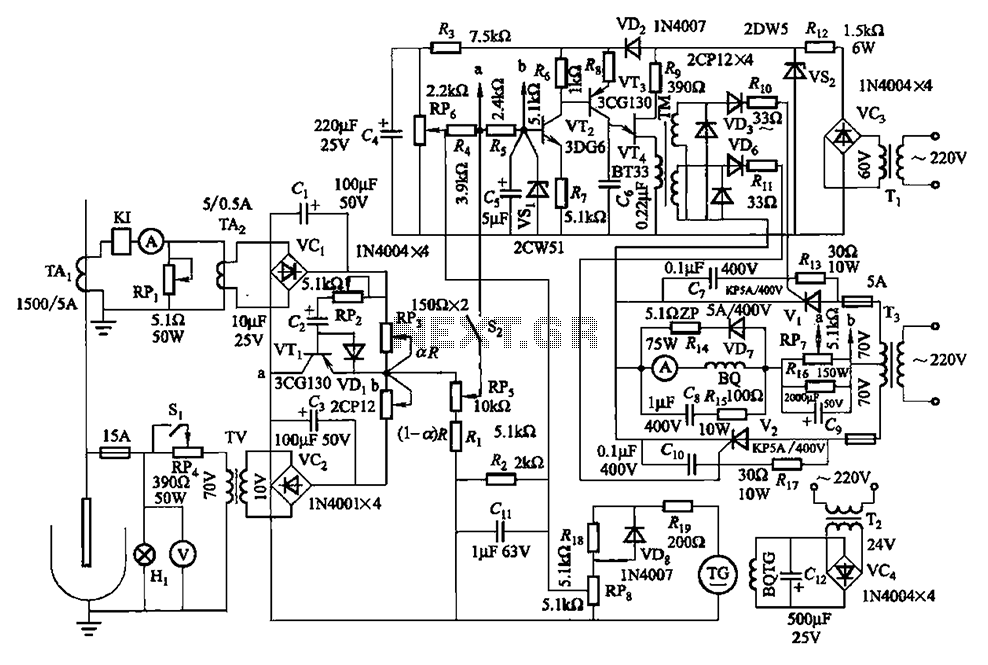
The circuit is illustrated in Figures 16-95 to 16-97. The electrode automatic adjuster demonstrates enhanced performance, featuring a high-accuracy, well-linear current output type bridge. Additionally, it incorporates a differential arc current negative feedback circuit (advanced) that allows for preemptive...