
circuit Making an obstruction avoiding device without microcontroller

The proposed circuit design involves a straightforward arrangement where two DC motors serve as the driving wheels for the toy device. The left motor is connected to an LDR positioned at the front of the device, which acts as a light sensor. The operational principle relies on the LDR's variable resistance in response to light intensity. Under normal conditions, when the device is in a well-lit environment and no obstruction is present, the LDR maintains a low resistance, allowing both motors to receive equal voltage and current. This results in the device moving forward in a straight line.
When an obstruction is encountered, the light intensity on the LDR diminishes, leading to an increase in its resistance. This change causes the voltage drop across the left motor to decrease, thereby reducing its speed while the right motor continues to operate at a constant speed. The differential in motor speeds induces a turning motion to the left, effectively allowing the device to navigate around obstacles.
To enhance the functionality and efficiency of the system, it may be necessary to incorporate additional components. For instance, an amplifier circuit could be integrated to boost the signal from the LDR, allowing for more precise control over the motor speeds. This would help in mitigating issues related to power dissipation within the LDR and ensure that the motors operate effectively without excessive energy loss.
Furthermore, it is critical to consider the specifications of the DC motors being used, particularly their current draw and operational voltage. With each motor drawing approximately 500 mA, it becomes essential to ensure that the power supply can accommodate the total current requirements of both motors. Additionally, the LDR's minimum resistance should be evaluated to ensure it does not adversely affect the motor performance. Implementing a resistor in series with the left motor may help balance the speeds of both motors, allowing for smoother operation and better obstacle avoidance.
In conclusion, while the proposed design is fundamentally sound, it requires careful consideration of component specifications and potential circuit improvements to achieve optimal performance. The integration of an amplifier for the LDR and appropriate balancing resistors can significantly enhance the reliability and efficiency of the device.Make a toy device which spins to the left whenever there is an obstruction in front of it, without any microcontroller. Can anybody please check whether my approach in building the device is correct or not [let`s assume we are driving our device in a bright room with uniform lighting] Any tips or suggestions for improvement (if it is correct) will also be appreciated.
My approach is to use two DC motors as the rear wheels of the device. Attach an LDR to the front of the device and connect it to the left motor. Now both the motors are connected to a power supply. When the power supply is switched on and no obstruction is in front of the toy, both the motors will be moving at approximately same speed since the LDR will be in exposure to light and its resistance will be negligible, because of which the toy will run straight. Now when there is some obstruction in front of the device, the amount of light falling on the LDR will decrease, which will imply a rise in resistance of the LDR.
Thus the velocity of the left motor will decrease, while the velocity of the right motor will be moreorless constant. So the device will spin to the left. The circuit diagram corresponding to my argument is provided in the link below. I will post the mechanical simulation of the device shortly (within 2 hours from now). In principle it will do what you expect but you`ll need to use the LDR into an amplifier so that the motor is controlled because its resistance is unlikely to be able to power much even when totally illuminated Andy aka Jun 1 `13 at 16:02 I am the one who asked this question [sorry for asking through the fake account, I was in a hurry actually].
Since I can`t comment I am posting it as an answer. @Andy aka, The LDR is not used to power the motor, instead it is used to reduce the velocity of the motor. Since the velocity of the other motor remains constant as it is not connected to the LDR, the vehicle should turn about the direction of the motor connected to the LDR.
abcd Jun 1 `13 at 17:15 What is the resistance of the LDR when it is lit Is it zero ohms Even if it is 10 ohms, you`ll need the equivalent of that resistance in the uncontrolled motor line to balance things to keep it in a straight line. How much current do the motors take 500mA If 500mA, at half motor speed from 6V battery, the power disippated in the LDR will be likely enough to torch it.
Andy aka Jun 1 `13 at 17:24 The motors take 500 mA current each. The LDR has minimum resistance nearly equal to 1 Ohms. The 1 Ohms resistor can be placed in the motor line to balance the speed of the motors. But do you think it will work I am currently designing the mechanical simulation of the device and will upload it soon. abcd Jun 1 `13 at 17:31 First, consider the kind of currents the motors in even a small toy would require.
Then consider how low a resistance the LDR would need to have so that the voltage drop to the right motor is negligible. It would probably need to be less than 1 ©, which is well below the practical range for LDRs. Even if this did work, it would not be very efficient and the LDR would dissipate significant power when it is in the half-on state.
Wasting power is not a good thing when batteries are in use. LDRs are much more suitalble as sensors instead of resistive pass elements for significant power. You have given no valid reason for avoiding a microcontroller, probably because there is none. If your reasons are religious, then your whole question is off topic here. This is a engineering site where we discuss solutions to real problems. A microcontroller reading light intensity from a LDR used as sensor, then driving each motor with PWM to modulate its drive level is the obvious and efficient way of doing this. With that setup, it would be simple to have two LDRs, one on each side, and have the device always drive towards the strongest light.
I see in some comments you made (now dele 🔗 External reference
Related Circuits
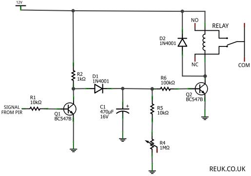
The focus is on 12 Volt DC powered PIR sensors and their associated circuits, which can be directly powered by a 12 Volt battery charged through renewable energy sources such as wind or solar. This article examines how the...
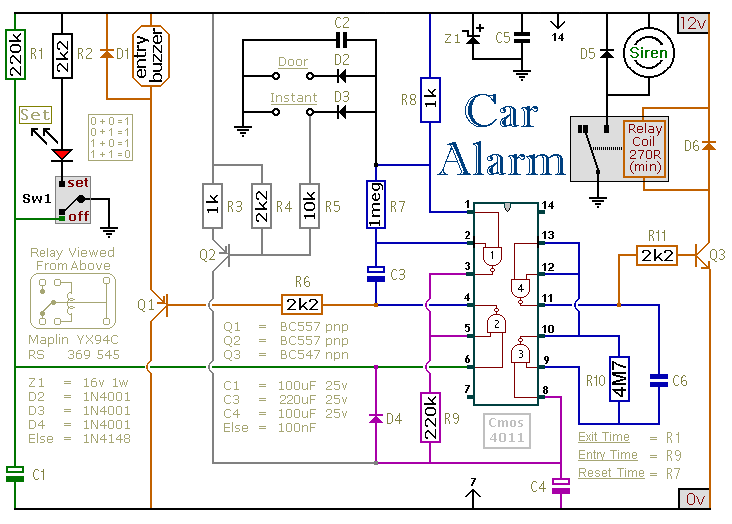
This circuit is designed to secure a vehicle at a low cost if constructed independently, making it more affordable than purchasing a commercial car alarm system. The alarm is activated by opening switch Sw1, which can be any small...
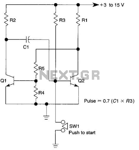
This circuit is activated when switch SW1 is pressed, grounding the base of transistor Q2. The pulse rate is approximately equal to 0.7 multiplied by the product of resistor R3 and capacitor C1. The described circuit features a transistor Q2,...
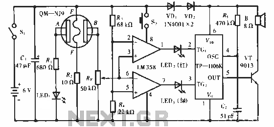
The QM-NJ9 is an alcohol sensor that detects the presence of alcohol by measuring the resistance values between points A and B. When alcohol is detected, the resistance decreases, leading to an increase in potential at point B. As...
This circuit provides a visual 9-second delay using 10 LEDs before closing a 12-volt relay. When the reset switch is closed, the 4017 decade counter is reset to the 0 count, illuminating the LED driven from pin 3. The...
Switching regulator subsystems are designed for use as DC to DC converters. The 3V to 40V DC converter circuit utilizes switching regulators, which are increasingly favored over linear regulators due to the demand for higher conversion efficiency in modern...