
3V to 40 Volt DC Converter Circuit Schematic Diagram

The MC34063 series is a versatile and efficient solution for DC to DC conversion, capable of handling various voltage levels and configurations. The internal components of the MC34063 facilitate seamless operation in diverse applications, such as battery-operated devices, power supplies for sensors, and automotive electronics. The temperature-compensated reference ensures stable output voltage across varying temperatures, which is critical for maintaining performance in real-world scenarios.
The comparator within the MC34063 monitors the output voltage and adjusts the switching duty cycle to maintain the desired output level, providing a robust feedback mechanism. The controlled duty cycle oscillator allows for efficient switching, reducing power loss and improving overall efficiency compared to linear regulators. The active peak current limit circuit protects the device and the load from excessive current, enhancing reliability and safety during operation.
In terms of implementation, the MC34063 can be configured for different modes of operation. For step-up (boost) configurations, the circuit can increase the input voltage to a higher output voltage, which is useful in applications where the input voltage is lower than the required output. Conversely, in step-down (buck) configurations, the circuit can reduce the input voltage to a lower output voltage. Additionally, voltage-inverting configurations allow for generating negative output voltages, expanding the range of applications.
The 8-pin dual in-line package makes the MC34063 easy to integrate into existing designs and prototyping setups. Its compact size and efficiency make it suitable for modern electronic devices that require space-saving solutions without sacrificing performance. Overall, the MC34063 series represents a reliable choice for engineers seeking to implement efficient DC to DC converters in their designs.Switching regulator subsystems intended for use as dc to dc converters. 3V to 40 Volt DC Converter circuit | The use of switching regulators is becoming more pronouncedover that of linear regulators because the size reductions innew equipment designs require greater conversion efficiency. Another major advantage of the switching regulator is that i thas increasednapplication flexibility of output voltage. The output can be less than, greater than, or of opposite polarityto that of the input voltage. The MC34063 series is a monolithic control circuitcontaining all the active functions required for dc to dc converters. This device contains an internal temperaturecompensated reference, comparator, controlled duty cycleoscillator with an active peak current limit circuit, driver, and a high current output switch.
This series was specificallydesigned to be incorporated in step up, step down andvoltage inverting converter applications. These functionsare contained in an 8 pin dual in line package. You are reading the Circuits of 3V to 40 Volt DC Converter Circuit And this circuit permalink url it is
🔗 External reference
Related Circuits
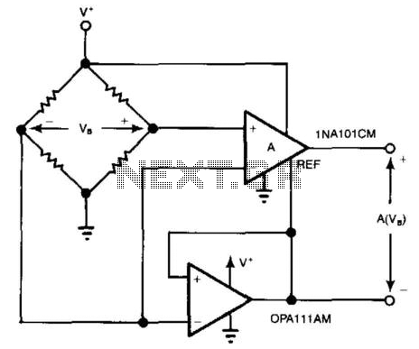
For systems with a single power supply, two operational amplifiers function as instrumentation and buffer amplifiers. The OPA111 AM buffers the reference mode of the bridge and applies that voltage to the reference terminal of the instrumentation amplifiers. The...
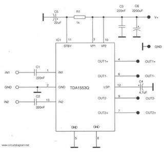
This is a 22-watt car stereo audio amplifier. The circuit is based on a single IC TDA1553 with a few peripheral components. This IC is designed for car audio applications. The TDA1553CQ integrates two 22-watt amplifiers with differential input...
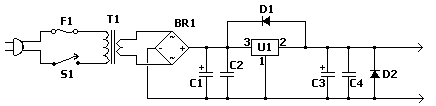
The fixed voltage power supply is useful in applications where an adjustable output is not required. This supply is simple, but very flexible as the voltage it outputs is dependent only on the regulator and transformer you choose. The...
Most peripherals that interface with a PC utilize a USB port. The computer's power supply circuit, specifically the switched-mode power supply (SMPS), is designed to provide constant power to all internal components. However, when external peripherals that require a...
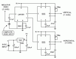
The VGA-to-Scope converter schematic has been simplified by removing op-amp buffers and inverters. A 1 Megohm potentiometer can be used instead of a continuous current supply to charge the capacitor from a 5V source. Proper placement of the potentiometer...
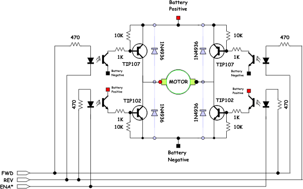
The opto-isolator LEDs are connected to three wires labeled "FWD," "REV," and "ENA." These wires serve as the interface between the bridge and the microprocessor. It is important to note that there is no "ground" signal present. When connecting...