
Circuit of power audio amplifier with circuit integrated tda2030 car amplifier 14 watts rms

The TDA2030 audio amplifier circuit is designed for versatility, allowing for various configurations to suit different audio applications. The typical application involves connecting the TDA2030 to a power supply that provides a voltage range suitable for the desired output. The circuit should include a transformer to step down the AC voltage, followed by a rectifier to convert the AC voltage to DC. Filter capacitors are essential to smooth out the DC voltage and minimize ripple, ensuring stable operation of the amplifier.
In terms of circuit protection, the inclusion of a 3-amp fuse in the positive supply line is crucial to prevent damage from overcurrent conditions. The fuse should be rated appropriately to allow normal operation while providing a safeguard against potential faults.
The use of a heat sink is also critical for the TDA2030 to dissipate heat generated during operation, especially when driving higher loads. The datasheet provides detailed specifications for selecting an appropriate heat sink based on the expected power output and thermal conditions.
For applications requiring increased output power, the TDA2030 can be configured in a bridge mode, effectively doubling the output power to 28 watts at 14V. This configuration is particularly advantageous for subwoofer applications in home theater systems, where enhanced bass response is desired.
When utilizing the TDA2030 in automotive applications, the circuit's ability to operate directly from a car battery is beneficial, allowing for portable audio solutions without the need for frequent recharging.
Overall, the TDA2030 is a robust and efficient choice for audio amplification, suitable for a wide range of applications from home theaters to portable audio systems. Its availability and affordability make it an attractive option for both hobbyists and professionals in the audio engineering field.TDA2030 is a circuit integrated monolithic in Pentawat ® package, to be used as class audio amplifier AB. Typically he supplies up to 14 Watts of potency (d=0. 5%) @ 14V/4 ©. The guaranteed potency is 12W in a load of 4 © and 8 watts in a load of 8 ©. Integrated him/it bill with circuits of component protection. Audio amplifier with having integrated tda2030, using source of simple feeding, for potency of 14 watts with a source of 15 volts. That source should be with transformer, rectificators and good filter capacitors, there is not need of regulated source. for protection of the circuit to use a fuse of 3 amperes in the line of +b of the amplifier. Use a heat-sink of heat in the circuit integrated tda2030. See the datasheet of the tda 2030 to know which heat-sink to use. That integrated it is cheaply and easy to find at the market. For a version in bridge for until 28 watts@14v and version using symmetrical source sees the datasheet of the tda2030.
That circuit can be fed by car batteries by good time without needing to recharge her. The tda2030 is usually found as amplifier of stage of potency of systems of home theater, it is in those that promise 1000 Watts of potency. For now a tda2030 supplies 14 watts, then 5 tda2030 supplies less than 100 watts rms. But that is a good idea, to use the tda2030 as amplifier of potency of systems surround, for the subwoofer the ideal is an assembly in bridge for more potency.
🔗 External reference
Related Circuits
The two circuits below illustrate the application of the 555 timer to activate a relay for a specified duration by pressing a momentary normally open (N/O) push button. The circuit on the left can be used for longer time...
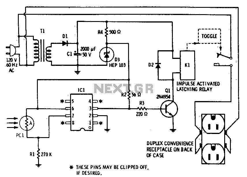
This device enables remote control of AC-powered appliances by utilizing the beam of a flashlight as a triggering mechanism. A key feature of this gadget is its memory function; activating it once supplies power to the device, and it...
This circuit is a conventional Pierce type oscillator that utilizes a JFET. It operates with fundamental mode crystals and exhibits good performance and reliability when a low noise JFET is employed. The feedback is regulated by the capacitance of...
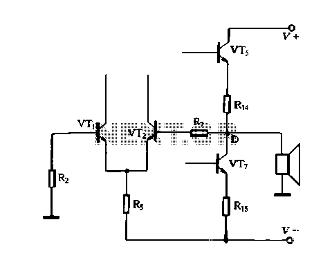
The DC feedback circuit is illustrated in Figure 1-31. In this circuit, resistor R7 is connected to the output terminal, which is the midpoint of the static differential input stage voltage Vr, between the base terminals. This configuration represents...
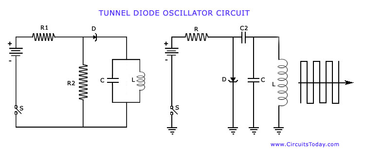
The operation of Negative Resistance Oscillators, including types such as Dynatron and Tunnel Diode Oscillator, along with their characteristics and circuit diagrams, is explained. Negative resistance oscillators are electronic circuits that exploit the phenomenon of negative resistance to generate oscillations....
This circuit is a constant current protection type that limits the output current to a specific value in cases of over-current and short-circuit conditions. When the output current exceeds this limit, the output voltage decreases. The CW200 power management...