
Negative Resistance Oscillators-WorkingTypesCircuitsCharacteristics

Negative resistance oscillators are electronic circuits that exploit the phenomenon of negative resistance to generate oscillations. These oscillators are characterized by their ability to sustain oscillations in the presence of negative resistance, which can counteract losses in the circuit.
The Dynatron oscillator, a specific type of negative resistance oscillator, utilizes a vacuum tube that exhibits negative resistance characteristics. In this configuration, the Dynatron operates in a region of its current-voltage (I-V) characteristic where an increase in voltage leads to a decrease in current, effectively providing the necessary conditions for oscillation. The circuit typically includes an LC tank circuit that determines the frequency of oscillation, with the tube providing the gain necessary to sustain oscillations. The output can be taken from either the anode or the cathode, depending on the desired application.
The Tunnel Diode Oscillator is another example of a negative resistance oscillator, which employs a tunnel diode that exhibits negative resistance at low voltages. The unique I-V curve of the tunnel diode allows it to operate in a region where it can provide gain, making it suitable for high-frequency applications. The circuit configuration usually involves a resonant circuit, consisting of inductors and capacitors, which sets the oscillation frequency. The simplicity of the tunnel diode circuit allows for compact designs, making it popular in RF applications.
Both types of negative resistance oscillators have distinct characteristics, such as stability, frequency range, and output power, which must be considered when selecting the appropriate oscillator for a specific application. The associated circuit diagrams illustrate the connections and components used in these oscillators, providing a visual representation of their operational principles. Understanding these elements is crucial for engineers designing circuits that require reliable oscillation sources.The working of Negative Resistance Oscillators,Types like Dynatron,Tunnel diode oscillator, their characteristics and circuit diagram is explained.. 🔗 External reference
Related Circuits
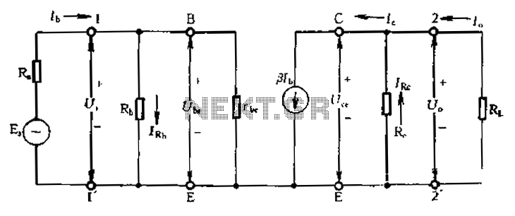
Calculate magnification, input resistance, and output resistance circuit. This circuit is designed to calculate the magnification, input resistance, and output resistance of a given electronic system. The magnification refers to the ratio of the output signal to the input signal,...
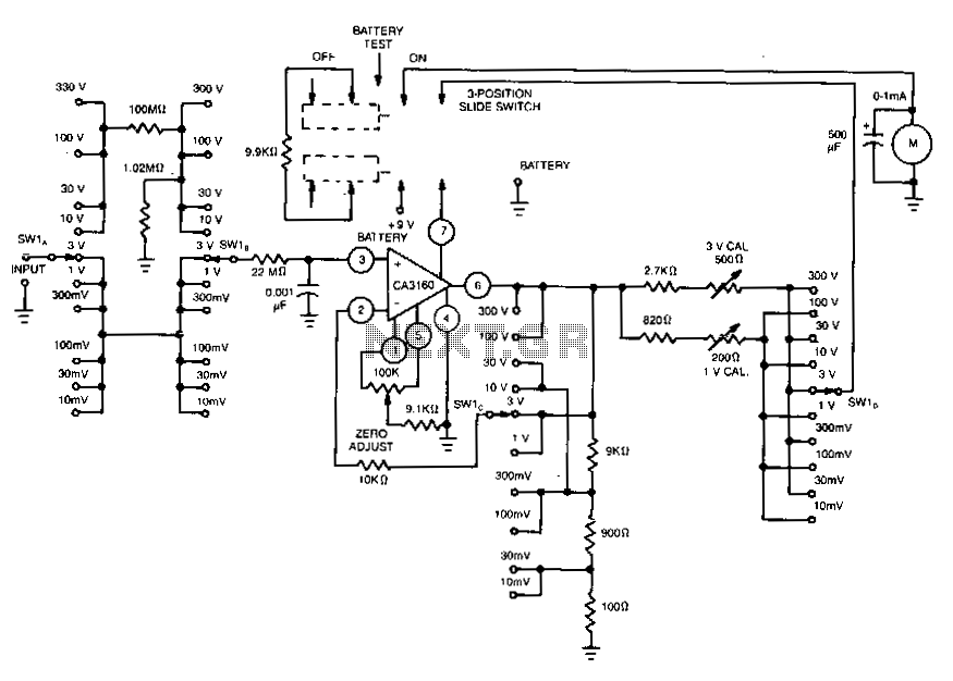
This voltmeter utilizes several beneficial characteristics of the CA3160 BiMOS operational amplifier. It offers voltage measurement capabilities ranging from 10 mV to 300 V. The circuit is powered by a single 8.4-V mercury battery and, at zero input, consumes...
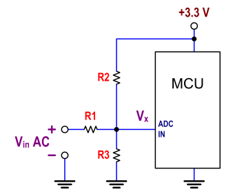
The ATtiny24 microcontroller's ADC is utilized to record an AC signal, which operates within a voltage range of 0 to 3.3V. A precision rectifier is employed to eliminate the negative portion of the signal. The circuit incorporates an LMC6484...
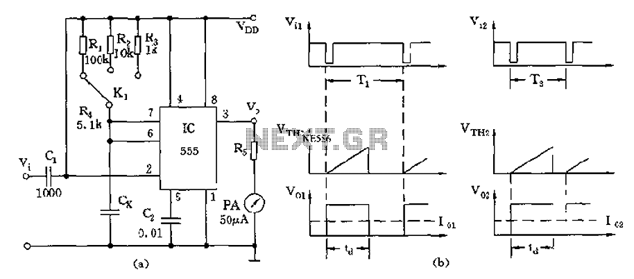
The circuit utilizes a 555 timer along with timing resistors R1 to R3 and a measured capacitance Cx to create a capacitance meter. The principle of capacitance measurement in a one-shot circuit is based on the relationship between the...
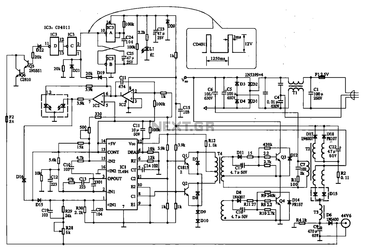
The TN-1 Intelligent Negative Pulse Charging Circuit is a sophisticated device designed for efficient battery charging. It operates as a half-bridge charger, which is a common configuration in such circuits. The negative pulse charging mechanism is facilitated by a...
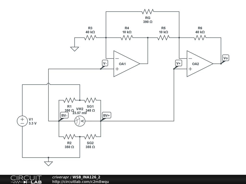
A half-bridge setup is utilized with strain gauges and an INA126 to amplify the voltage. The voltage can be read accurately when the lever is bent in one direction; however, no reading is obtained when the lever is bent...