10 Step Baby Gate Sequencer CD4017
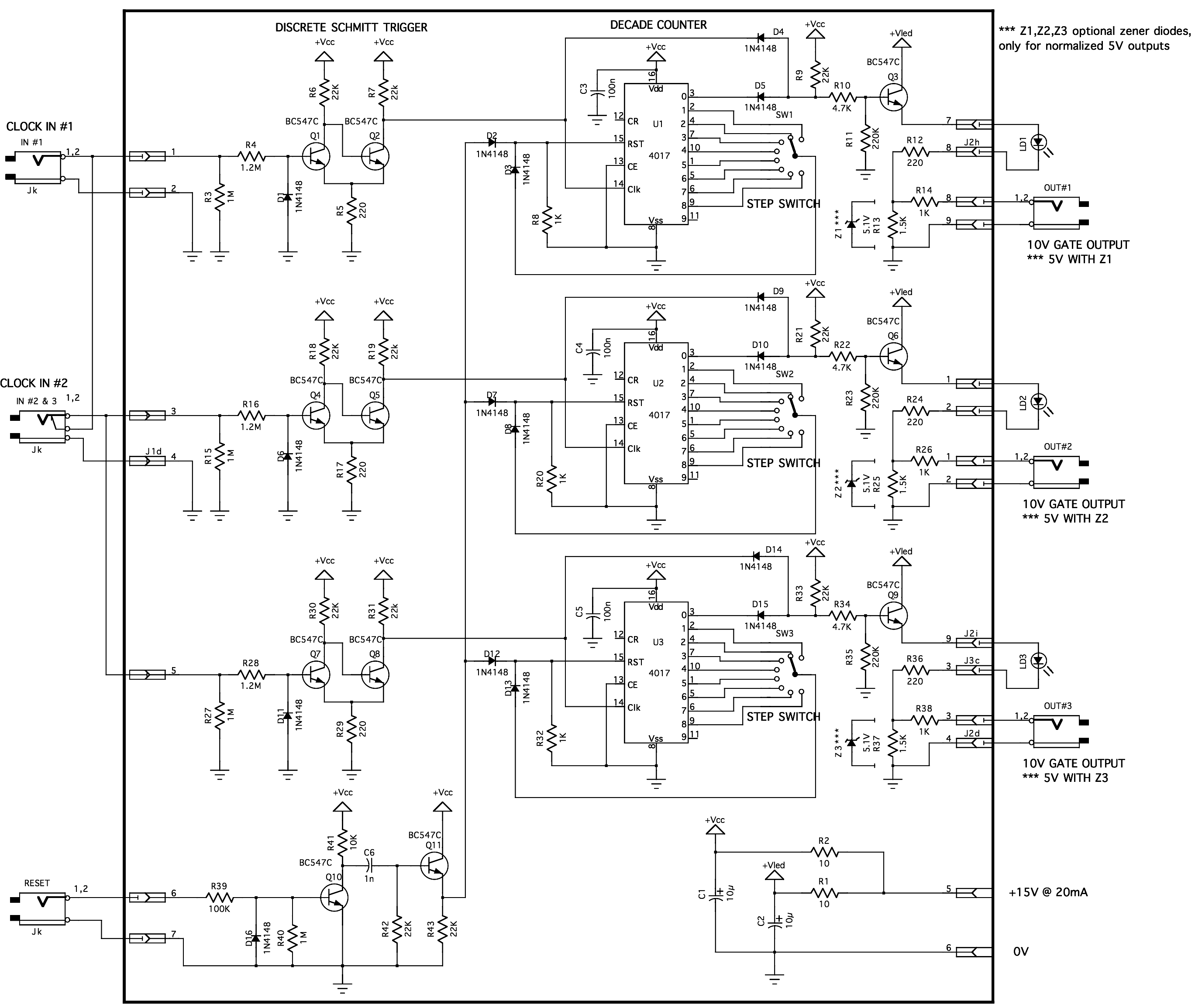
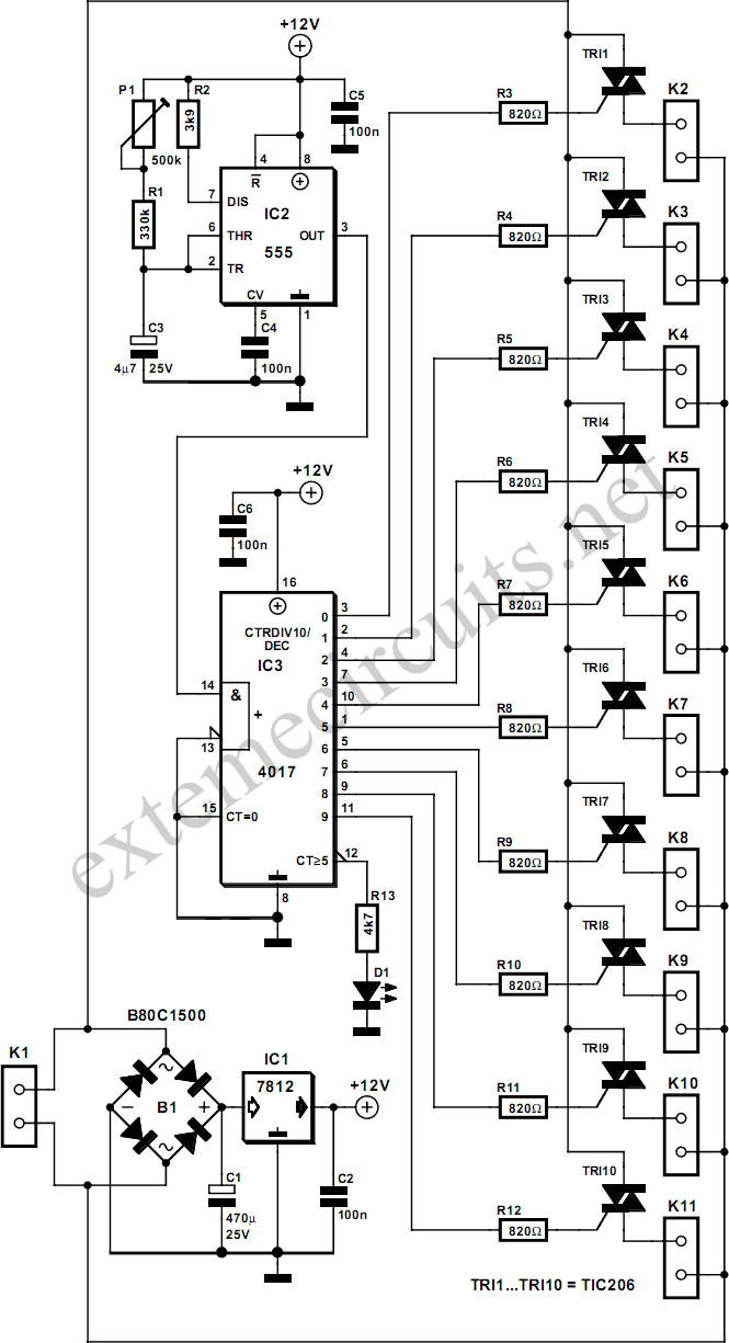
The latest version of the "baby 10 sequencer" has been completed, featuring control voltage and gate switches. Some issues were encountered with the module, and modifications are planned for the near future. In preparation for enhancing the baby 10 sequencer, ideas involving the CD4017 have been explored. Recently, a sub-oscillator was constructed using the CD4017, which led to the discovery of a two-transistor Schmitt trigger derived from the Yusynth clock divider. Additionally, a diode "AND" gate was adapted from the same clock divider for this project. A "gate to trigger" circuit, inspired by Ken Stone's design, was incorporated for the reset sync input. The originality of the module's design is uncertain, but it serves as a valuable learning experience. This circuit will facilitate the development of a comprehensive 10-step baby sequencer as a potential future project. A novel idea emerged during the panel layout process, as rotary switches were deemed cumbersome and costly. Due to space constraints for inputs, outputs, switches, and LEDs within a single module width, a SPDT (on/off/on) switch was devised to manage both the gate and reset functions. The switch positions are configured as follows: gate one, gate off, and reset. It is important to note that having multiple switches in the reset position will cancel the reset function. While this issue could be resolved by adding diodes, it was determined that it was unnecessary since users must ensure that only one switch is set to reset at any given time, unlike with a rotary switch.
The "baby 10 sequencer" circuit utilizes the CD4017 decade counter, which is capable of counting from 0 to 9, making it suitable for sequencing applications. The control voltage inputs allow for modulation of the sequencer's behavior, enabling creative musical applications. The inclusion of gate switches enhances the functionality by allowing for the triggering of external devices or sound modules.
The two-transistor Schmitt trigger provides a reliable means of signal conditioning, ensuring that the output remains stable despite fluctuations in input voltage levels. This is particularly advantageous in sequencing applications where precise timing is crucial. The diode "AND" gate facilitates logical operations within the circuit, allowing for more complex sequencing patterns and interactions with other components.
The gate to trigger circuit implemented for the reset sync input ensures that the sequencer can be synchronized with external clocks or triggers, enhancing its versatility in performance settings. The design choice to use a SPDT switch instead of a rotary switch not only saves space but also simplifies the user interface, making it more intuitive for users to operate the sequencer.
Overall, the design choices made in this version of the baby 10 sequencer reflect a thoughtful approach to circuit functionality and user experience, paving the way for future enhancements and more advanced sequencing capabilities.I Just finished my newest version of the "baby 10 sequencer". It has control voltage and gate switches. I found some problems with it, and subsequently this module. I will be posting some modifications in the next few days. In preparation of improving my baby 10 sequencer, I`ve been coming up with things to do with the CD4017. A couple weeks ago I built the sub-oscillator out of the CD4017. That introduced me to the 2 transistor Schmitt Tigger which I borrowed from the Yusynth clock divider. I also borrowed from that same clock divider, a diode "and" gate which I modified for this project. I also chose to incorporate a "gate to trigger" circuit similar to Ken Stones Gate to tigger circuit for my reset sync input.
I`m not sure how much of this module you could actually call mine, but I guess this is how you learn at first. Working out this circuit will be a big help when I move onto my all encompassing 10 step baby sequencer.
possibly my next project. I came up with a cool idea too as I was trying to do the panel layout. I hate rotary switches! they are expensive and I find them to be panal hogs. There just wasn`t enough room to incorporate all the inputs, outputs, switches and LEDs I wanted in a single module width while still having that clunky 10 position rotary switch. So I came up with an idea of using a SPDT(on/off/on) switch to control the gate as well as the reset.
the positions work like this (gate one/gate off/ Reset). One thing to be noted is that having more than a single switch in the reset position will cancel the reset out. This could be fixed by adding diodes but I felt that would be mostly unnecessary and would add 10 diodes the PCB, when really, all you have to do is not have 2 switches set to reset at the same time (something you don`t have to worry about with a rotary switch)
🔗 External reference
