
Step-Down Converter Controller

The TPS6420x controller is an advanced power management solution that efficiently converts input voltages from a range of sources, including series-connected lithium-ion cells or regulated USB power supplies. Its output capability of 3.3 V at 2 A makes it particularly well-suited for microcontroller applications, ensuring stable power delivery even under varying load conditions.
The design flexibility of the TPS6420x is notable, as it allows for adjustments in output voltage and current through the selection of external components, such as inductors, P-channel MOSFETs, and Schottky diodes. The device's low quiescent current consumption in power-down mode and during no-load operation enhances its energy efficiency, making it ideal for battery-operated devices where power conservation is critical.
The asynchronous step-down conversion mechanism employed by the TPS6420x differentiates it from conventional PWM and PFM controllers. By maintaining a constant on-time and/or off-time, the controller optimizes performance across a wide load range while minimizing switching losses. This ability to adapt the switching frequency based on load conditions further enhances efficiency, particularly in applications where load demands fluctuate.
In practical applications, the TPS6420x can be configured to handle an extensive output voltage range from 1.2 V up to the input voltage, accommodating various system requirements. The inclusion of a shunt resistor for current limiting provides an additional safety feature, preventing excessive current draw that could potentially damage connected components.
The controller's operation in discontinuous mode at low output currents allows for a smooth transition during varying load conditions, while continuous conduction mode ensures stable performance at higher currents. The use of Schottky diodes and MOSFETs with appropriate specifications is crucial for maintaining efficiency and reliability, particularly in high-frequency switching applications.
Overall, the TPS6420x controller represents a robust solution for modern power management needs, offering versatility, efficiency, and reliability across a broad spectrum of electronic applications.The TPS6420x controller is designed to operate from one to three series-connected cells or from a 3. 3 V or 5 V supply obtained from a USB port. At its output it can produce 3. 3 V at 2 A, suitable for powering a microcontroller-based system. With a suitable choice of external components (inductor, P-channel MOSFET and Schottky diode) the device can be operated over a wide range of possible output voltages and currents. A further advantage is its extremely low quiescent current consumption in power-down mode (100 nA typical) and in no-load operation (20 mA). Also, if the input voltage is less than or equal to the desired output voltage, the device can connect the output directly to the input.
Using just a few external components the TPS6420x can cover an output voltage range from 1. 2 V up to the input voltage at up to 3 A, as long as a suitable P-channel MOSFET and Schottky diode are used. The device is an asynchronous step-down converter which, unlike the more widely-used PFM (pulse-frequency modulation) and PWM (pulse width modulation) types, involves a constant on-time and/or constant off-time.
Conventional controllers operate in PWM mode at medium to high loads, switching to PFM at lower loads in order to minimise switching losses. The controller described here also adjusts its switching frequency in accordance with the load to achieve a similar effect to the PFM/PWM controllers.
The circuit diagram shows a classical step-down converter with an input voltage range from 3. 3 V to 6 V and an output voltage of 3. 3 V at a current of up to 2 A. The optional 33 m shunt resistor provides for current limiting. The TPS64202 offers a minimum on-time selectable between 1. 6 ms, 0. 8 ms, 0. 4 ms and 0. 2 ms and a fixed off-time of 300 ns. A MOSFET in the supply voltage path is switched on by the controller for as long as is necessary for the output voltage to reach its nominal value, or until the maximum permissible current, as determined by the shunt resistor, is reached. If the current does exceed this limit the MOSFET is switched off for 300 ns. If the nominal output voltage is reached, the MOSFET is switched off and remains in the off state until the output voltage once again falls below the nominal value.
At very low output currents the controller therefore operates in discontinuous mode` (DCM). Each switching cycle begins with the current at zero. It rises to the threshold or maximum value, and then falls again back to zero. At the moment of switch-off the Schottky diode causes the residual energy in the inductor to appear as a quickly-decaying oscillation at the resonant frequency of the output filter. This low-energy oscillation in discontinuous mode is normal and has no adverse effect on the efficiency of the converter.
It can be damped using the (optional) RC series network. At higher output currents the switch-down converter operates in continuous conduction mode (CCM). In this mode the inductor current never falls to zero. The output voltage is directly proportional to the switching mark-space ratio in this mode. If the Si2323 P-channel MOSFET from Vishay-Siliconix is not available, the IRLML6401 (12 V type) or IRLML6402 (20 V type) from IRF can be used instead. Both these types have a higher on resistance, but do offer a lower gate capacitance. An alternative for the Schottky diode suggested is the MBRM140 (available from Digi-Key and Farnell), although this is in an SMB package rather than the Powermite package of the MBRM120.
The voltage drop at 1 A is somewhat higher: 0. 6 V instead of 0. 45 V. The devices are manufactured by IRF and ON Semiconductor. 🔗 External reference
Related Circuits
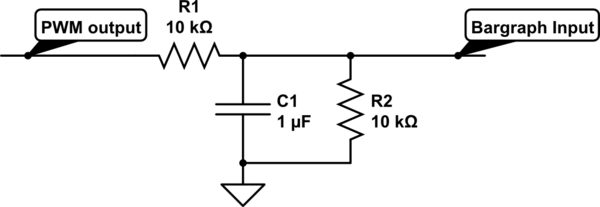
For a project, there is a need to display a progress bar representing the activity performed by a microcontroller unit (MCU). A bar graph display is intended for this purpose; however, the bar graph display driver IC, LM3914, requires...
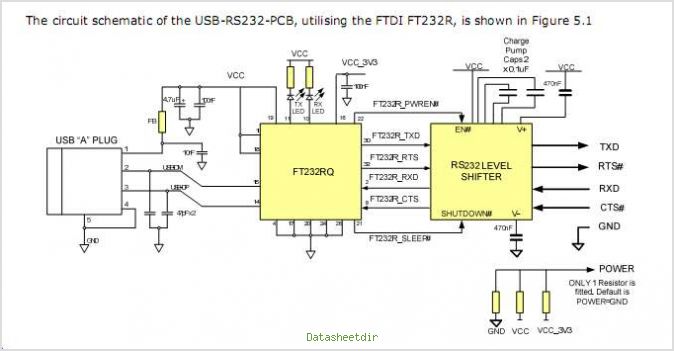
The USB-RS422-PCB is a printed circuit board (PCB) designed as a USB to RS422 level serial UART converter. It utilizes FTDI's FT232RQ USB to Serial UART Interface IC, which manages all USB signaling and protocols. This PCB offers a...
If you are looking for ICs for a DC to DC converter application, the LM1577/LM2577 ICs are highly recommended as they provide all the necessary power and control functions for step-up conversion. The LM1577 and LM2577 are versatile integrated circuits...
A relay-based on/off controller on the other hand can be very efficient. A typical relay has a contact resistance of 3 milliOhm. At 20A, this translates to a voltage drop of 0.06 volts, with a power loss of 1.2W....
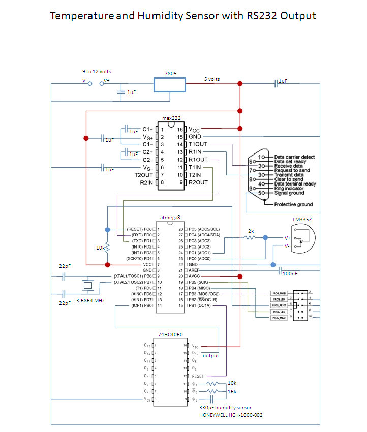
This is an affordable method for measuring temperature and humidity with a computer interface, designed as an entry-level project for high school students on a limited budget. The project involves the integration of a temperature and humidity sensor, such as...
This is a very sensitive 50Mc converter allowing you to receive the entire "Magic Band" (50Mc...52Mc) on your general coverage receiver (28Mc...30Mc). It receives all types of modulated transmissions. It all depends on the receiver used. I’ve tested this...