
stepper motor interfacing with spartan 3an fpga

The Spartan-3an board is designed to facilitate the control of stepper motors through a robust interfacing mechanism. The ULN2803A is a crucial component in this setup, providing the necessary current amplification to drive the motor effectively. This Darlington transistor array consists of eight high-voltage, high-current transistors, which are configured to operate as a low-side switch. The use of Darlington pairs allows for higher current gain, making it suitable for driving inductive loads such as stepper motors.
In the schematic, the stepper motor's control lines are connected to the output pins of the ULN2803A. Each output pin corresponds to a specific phase of the stepper motor, allowing for precise control of the motor's rotation direction and step increments. The inputs of the ULN2803A are connected to the I/O ports of the Spartan-3an board, which are configured to send control signals based on the desired motor operation.
The PTB connector on the board is an important feature, as it allows for the connection of an external power supply. This is particularly useful when the stepper motor requires more current than the board can provide through its I/O ports. By connecting an external power source to the PTB connector, the ULN2803A can draw the necessary power to drive the motor without overloading the board's power supply.
In summary, the Spartan-3an board's design for stepper motor interfacing exemplifies the integration of digital control with high-current drive capabilities, enabling efficient and effective motor control in various applications.The Spartan-3an board has external stepper motor interfacing, indicated as in Figure. Stepper Motor is driven by ULN2803A. It is a high-voltage, high-current Darlington transistor array. ULN2803 is used as a driver for port I/O lines, drivers output connected to stepper motor, PTB connector provided for external power supply if needed. 🔗 External reference
Related Circuits
The following diagram is for the main circuit of the motor driver. A testing version is shown near the end of this page. It is laid out differently and shows the SN7474 in logic block form and LEDs are...
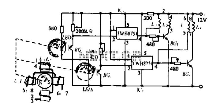
To activate a water magnet, the stator coil is divided into four groups. Each set of coils is controlled by pulse signals generated by the rotor, creating a rotating magnetic field. This operation is facilitated by controlling the signals...
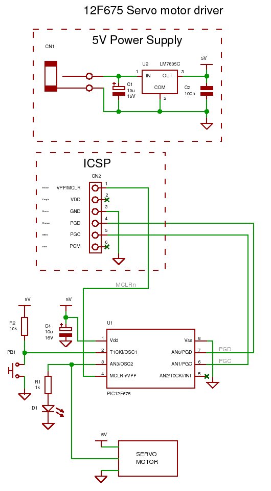
How to generate the signal for controlling a standard (RC) servo motor using a PIC microcontroller. To control a standard RC servo motor with a PIC microcontroller, it is essential to generate a pulse-width modulation (PWM) signal that dictates the...
The first step is to measure the amplification factor of the end transistors (T3 and T4), known as the hfe. If their difference exceeds 30%, the amplifier will produce unclear sound. In this case, MJ3001 and MJ2501 transistors were...
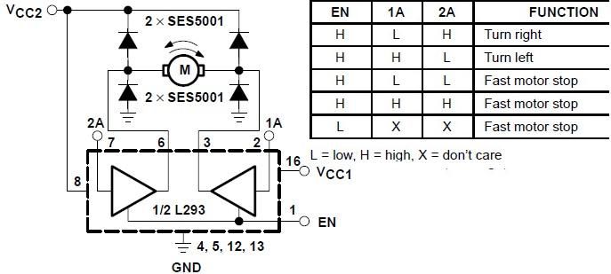
The L293 is designed to provide bidirectional drive currents of up to 1 A at voltages ranging from 4.5 V to 36 V. The L293D variant is capable of delivering bidirectional drive currents of up to 600 mA at...
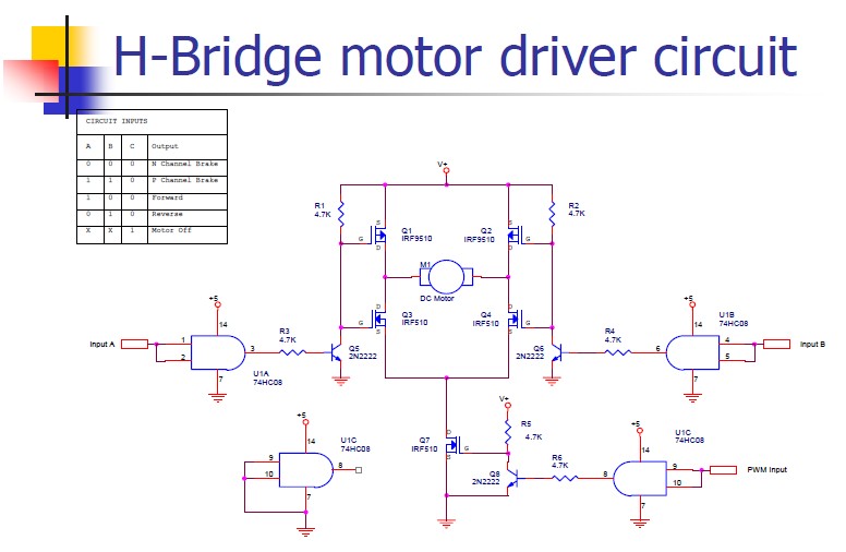
An H-bridge motor driver circuit is designed to control a DC motor. By using a low signal, such as a 5-volt signal, the circuit enables the program to manage the motor, which operates on a higher power supply. The H-bridge...