
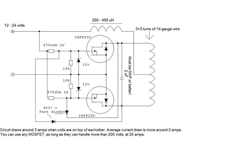
16 step sequencer schematic

The described 16-step sequencer utilizes three integrated circuits to create a fully analog system capable of generating complex sequences without relying on digital controllers. The primary component, the 4015 dual 4-bit shift register, enables the storage and manipulation of step data. Each of the two registers can hold a sequence of four bits, allowing the sequencer to produce a total of 16 distinct steps. The variable speed control can be implemented using a variable resistor or potentiometer connected to the clock input of the 4015, enabling users to adjust the tempo of the sequence dynamically.
The design also incorporates an arpeggio function, which can be achieved by manipulating the output of the shift registers to create ascending or descending patterns based on the input voltage levels. This feature can be useful for musical applications, allowing for more expressive and varied output.
It is crucial for builders to pay attention to the capacitor connections, as incorrect polarity can lead to circuit failure. Capacitors should be oriented according to their markings, with the negative lead connected to ground or the lower voltage side of the circuit. Understanding the pin configuration for the 4015 is also essential, as this will determine how the shift registers are wired and how the sequencer operates.
The additional illustrations, such as the previously mentioned 8-step sequencer, serve as valuable references for understanding the layout and connection of components. They provide insights into the necessary parts, including the CV output potentiometer and plugs, which are crucial for interfacing the sequencer with other devices or synthesizers. By studying these diagrams, builders can gain a comprehensive understanding of how to construct a reliable and functional analog sequencer.After a lot of searching the web, I could not find a 16 step sequencer schematic that didn`t require an arduino or PIC or some other digital controller. Here is a simple 3 chip analog 16 step sequencer with variable speed and arpeggio I came up with, based off many other inspirations as noted in the file.
The I Cs in the middle are pin-diagrams, arranged like this since a 4015 is actually two 4-bit shift registers in each chip, so each 4015 has 16 pins but the IC numbers indicate IC1 and IC2 (IC = integrated circuits, AKA chips. ) If you`re new at building sequencers, make sure to learn how to tell the polarity of capacitors connections and the way to figure out pins.
Check my other illustration ( 8-step sequencer ) for diagrams and other important parts listed of a fully functioning machine. For example, the CV output pot and plugs are described in more detail on that schematic but not here.
🔗 External reference
Related Circuits
To construct the circuit, follow the provided schematic. If assistance is required, do not hesitate to reach out for support. If there are difficulties in identifying the components... To build the circuit effectively, it is essential to adhere closely to...
This application note presents alternate RF matching networks for the MAX2653 SiGe LNA, tuned for the GPS band (1575 MHz center frequency). Performance metrics (supply current, forward gain, noise figure, IIP3, reverse isolation, and input/output return loss) for both...
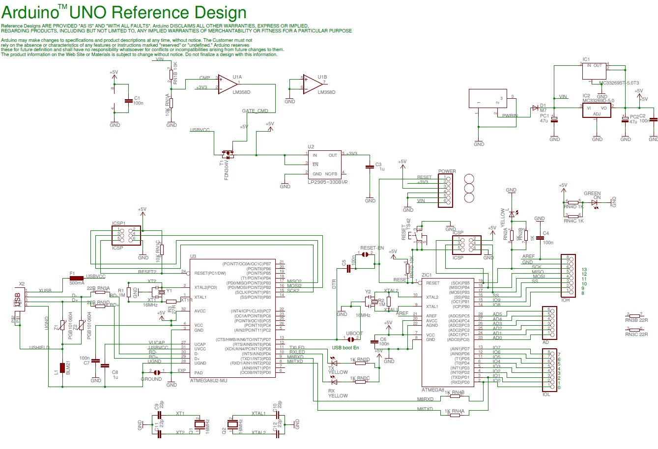
The Arduino Uno schematic diagram is available for viewing. The Arduino Uno is a microcontroller board that utilizes the ATmega328 chip. It features 14 digital input/output pins, of which 6 can function as PWM outputs, along with 6 analog...
The controller for a Hybrid Power Plant (HPP) block diagram consists of 440 Wp photovoltaic modules, a 1 kW wind turbine, and a 5 kW diesel engine as a backup. The HPP functions as a centralized PV and wind...
Two-Tone Siren Circuit Schematic Using One IC. This circuit is designed for children's entertainment and can be installed on bicycles, battery-powered cars, motorcycles, as well as models and various games and toys. It includes a switch (SW1) for operation. The...

This circuit can for example be incorporated into a diet to pressure warning. The meter can measure voltages from -99 mV to 999 mV. The circuit uses two ICs, the CA 3161 and CA 3162. IC1 converts the analog...