
211 SET amp built
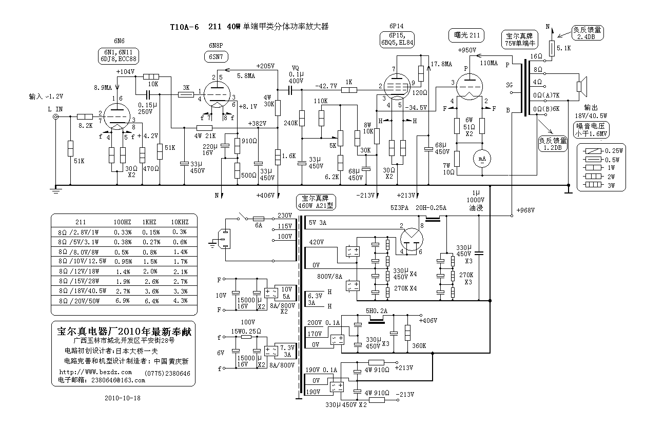
The amplifier in question is a high-fidelity audio device, characterized by its use of 211 vacuum tubes, which are known for their ability to deliver high-quality sound. The unit's unused condition, indicated by the presence of the protective plastic film, suggests that it has not been subjected to operational wear, making it a potentially valuable component for audio enthusiasts or professionals.
However, the presence of a loose component within one of the 211 tubes raises concerns regarding the integrity and functionality of the circuit. This issue necessitates the replacement of the affected tube to ensure optimal performance. The 211 tube typically operates in a high-voltage environment and is critical for amplification stages within the circuit.
The inquiry regarding the positioning of the six smaller valves indicates a need for clarity on the circuit layout. Proper placement of these valves is essential for maintaining signal integrity and achieving the desired tonal characteristics of the amplifier. The schematic should provide detailed information on the pin configuration and layout to facilitate accurate installation.
Additionally, the question about speaker impedance is crucial, as the amplifier's performance can be significantly affected by mismatched impedance. The selection of appropriate speakers, typically rated in ohms, must align with the amplifier's output specifications to prevent damage and ensure efficient power transfer. Common impedance values for speakers range from 4 to 16 ohms, and the amplifier's manual or specifications should provide guidance on the optimal impedance for use.
In summary, the amplifier requires attention to both the replacement of the defective 211 tube and clarification on the valve positioning and speaker impedance to ensure proper functionality and performance. A detailed schematic would be beneficial in addressing these concerns, providing a comprehensive overview of the circuit design and component specifications.The amp appears to be unused, still has the plastic film stuck to it. One of the 211`s has a loose component rattling around inside so we will need to get one of those. As I said in my earlier post, it is the possitioning of the 6 smaller valves that we are stuck for and what ohms speakers to use. Anyone know Thanks The amp appears to be unused, still has the plastic film stuck to it. One of the 211`s has a loose component rattling around inside so we will need to get one of those. As I said in my earlier post, it is the possitioning of the 6 smaller valves that we are stuck for and what ohms speakers to use. Anyone know Thanks 🔗 External reference
Related Circuits
Here is a 12 volt / 2 amp lamp dimmer that can be used to dim a standard 25 watt automobile brake or backup bulb by controlling the duty cycle of an astable 555 timer oscillator. When the wiper...
When constructing a dual stand-alone preamplifier, such as a stereo magnetic phono preamp, the power supply requirements are significantly reduced. A simple power supply circuit is illustrated, utilizing readily available 12-volt, 0.5-ampere transformers, although units capable of 1 ampere...
While I would have liked a 4 channel chip with about 20 Watt per channel, the local parts store didn't have any yet, so I opted for two TA8215AH stereo chips, selected by their low price in this particular...
This circuit deactivates an amplifier or any connected device when a low-level audio signal at its input is absent for at least 15 minutes. By pressing P1, the device is powered on, supplying power to any appliance connected to...
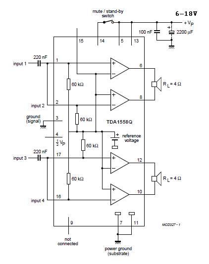
A 22W x 2 audio amplifier circuit diagram utilizing the TDA 1558 integrated circuit from Philips. The TDA1558 is a monolithic integrated class-B output power amplifier housed in a 17-lead single-in-line (SIL) plastic package. This amplifier operates based on...
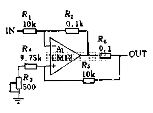
In a servo system, the current drive connection is frequently utilized. The output current (IOUT) is proportional to the input channel number (y). Using the current drive mode can mitigate issues caused by the motor's large inductance, which induces...