
4040B LED Counter
In this circuit, a counter is utilized to count the number of input pulses. The output of the counter is connected to a light-emitting diode (LED), which serves as a visual indicator of the pulse count. When pulses are received at the input, the counter increments its count, and each increment can be represented by the LED's illumination.
To design this circuit, the following components are typically used:
1. **Counter IC**: A digital counter IC, such as the 4017 decade counter or a binary counter like the 74HC393, is employed to count the incoming pulses. The counter IC will be powered by a suitable voltage supply, typically between 3V to 15V, depending on the specific IC used.
2. **Input Signal**: The input signal can be generated from various sources, such as a switch, a sensor, or a waveform generator. The input pulses should be within the operational frequency range of the counter IC.
3. **LED**: The LED is connected to one of the output pins of the counter. A current-limiting resistor is also required in series with the LED to prevent excessive current from flowing through it, which could damage the LED. The resistor value can be calculated based on the supply voltage and the forward voltage drop of the LED.
4. **Power Supply**: A stable power supply is essential for the reliable operation of the circuit. The voltage should match the requirements of both the counter IC and the LED.
In operation, as the input pulses are received, the counter increments its output. The LED will light up each time the counter reaches a specific output state, providing a clear visual indication of the pulse count. This setup is particularly useful in applications where monitoring pulse counts visually is necessary, such as in educational demonstrations or simple counting applications.
Overall, this circuit effectively combines digital counting with a visual output, facilitating easy monitoring of pulse activity.The number of the pulses of the input can be confirmed by seeing it with the eyes by putting the light-emitting diode to the output of the counter .. 🔗 External reference
Related Circuits
A discussion took place on synth-diy regarding the challenges of constructing a voltage-controlled oscillator with a sawtooth wave output, where the duty cycle (the ratio of ramp-up time to ramp-down time) can be adjusted using a separate control voltage....
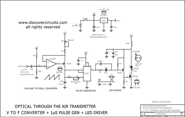
This circuit receives the signal from the amplifier and emits powerful 1μs infrared light pulses from a low-cost LED, which are frequency modulated by the audio information. The 10kHz center frequency of the pulse stream is sufficiently low, allowing...
This simple and inexpensive circuit built around a popular CMOS hex inverter IC CD4069UB offers four sequential switching outputs that may be used to control 200 LEDs (50 LEDs per channel), driven directly from mains supply. Input supply of...
This design synthesis considers the accuracy of frequency measurement and the requirements for response time. For instance, when measuring a frequency of 1 Hz, the measurement duration must exceed 1,000 seconds to accurately count the gate width. To ensure...
This is a directly coupled (DC) amplifier circuit. It is constructed using NPN and PNP transistors and is designed to amplify direct current (DC) signals. The directly coupled amplifier circuit utilizes both NPN and PNP transistors to achieve its amplification....
The circuit is a comparator that can measure the voltage of a car battery in steps of 1 Volt. The voltage is determined after comparing the voltage of the battery, which is applied to the inverting inputs of amplifiers,...