
200 LEDs Christmas Lights circuit
The circuit utilizes a CD4069UB CMOS hex inverter as the primary control element, which is a versatile component capable of performing various logic functions. The circuit is designed to operate directly from a 230V AC mains supply, which is first converted to a lower DC voltage suitable for the inverter IC. The bridge rectifier configuration (D1 to D4) ensures that the AC input is converted to a pulsating DC output. The filtering stage, composed of capacitor C1 and resistor R5, smooths the rectified output, yielding approximately 6V DC, which is then used to power the CD4069UB.
The inverter's six gates are effectively utilized, with the first four gates (N1 to N4) tasked with driving high-voltage transistors (T1 to T4). These transistors, specifically 2N3440 or 2N3439, serve as switches for four separate channels, each capable of controlling 50 LEDs. Current limiting resistors of 10 kΩ are employed to ensure that the LEDs operate within safe current limits, preventing damage due to excessive current flow.
To facilitate fine-tuning of the transistor operation, variable resistors (10 kΩ pots) are integrated into the base drive paths of the transistors, allowing for adjustments to the base current and consequently the brightness of the LEDs. The remaining two gates (N5 and N6) are configured to create a low-frequency oscillator, which is essential for generating a sequential switching effect for the LED channels. The frequency of this oscillator can be modified by adjusting the variable resistor VR1, providing flexibility in the operation of the LED sequence.
For optimal performance of the oscillator, it is recommended to use a high-quality, low-leakage capacitor for the timing capacitor C2, as this will ensure stability and accuracy in the frequency generation. Overall, this circuit design offers an efficient and cost-effective solution for controlling multiple LED channels directly from a mains supply, leveraging the capabilities of the CD4069UB inverter IC. This simple and inexpensive circuit built around a popular CMOS hex inverter IC CD4069UB offers four sequential switching outputs that may be used to control 200 LEDs (50 LEDs per channel), driven directly from mains supply. Input supply of 230V AC is rectified by the bridge rectifiers D1 to D4. After fullwave rectification, the average output voltage of about 6 volts is obtained across the filter comprising capacitor C1 and resistor R5.
This supply energises IC CD4069UB. All gates (N1-N6) of the inverter have been utilised here. Gates N1 to N4 have been used to control four high voltage transistors T1 to T4 (2N3440 or 2N3439) which in turn drive four channels of 50 LEDs each through current limiting resistors of 10-kilo-o Base drive of transistors can be adjusted with the help of 10-kilo-ohm pots provided in their paths. Remaining two gates (N5 and N6) form a low frequency oscillator. The frequency of this oscillator can be changed through pot VR1. When pot VR1 is adjusted To get the best results, a low leakage, good quality capacitor must be used for the timing capacitor C2
🔗 External reference
Related Circuits
This regulated power supply can be adjusted from 3 to 25 volts and is current limited to 2 amps as shown, but may be increased to 3 amps or more by selecting a smaller current sense resistor (0.3 ohm)....
Many households are still equipped with tube-type television sets. If there is a desire to connect one of these large televisions to a stereo system to enhance the sound quality... To connect a tube-type television to a stereo system, it...
Electronics tutorial on mesh current analysis and examples of mesh analysis used to analyze complex electrical circuits in DC theory. Mesh current analysis is a powerful technique used in circuit analysis to determine the currents flowing in the loops of...
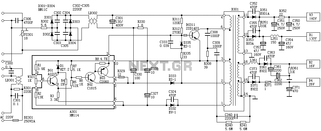
Oscillation: The positive terminal voltage of C310 is approximately 300V. The resistors R311 and R312 are connected to the switch BG311 at the B pole, while the B301 winding via the switching transformer (4) and (6) is connected to...
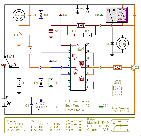
This is an improved version of the basic Garage/Shed Alarm. The Entry and Exit delays have been extended to approximately 30 seconds, and a timed Siren cut-off along with an automatic reset feature has been added. Additionally, the LED...
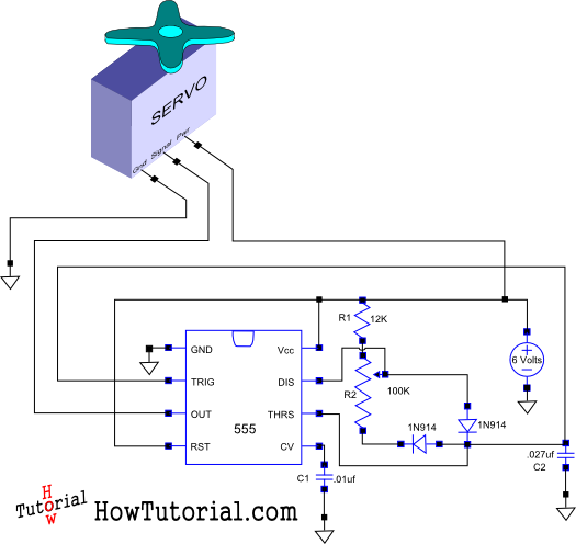
This document outlines the design of a simple circuit that enables control of a servo motor and allows for testing its functionality. The circuit for controlling a servo motor typically consists of a microcontroller, a power supply, and the servo...
Warning: include(partials/cookie-banner.php): Failed to open stream: Permission denied in /var/www/html/nextgr/view-circuit.php on line 713
Warning: include(): Failed opening 'partials/cookie-banner.php' for inclusion (include_path='.:/usr/share/php') in /var/www/html/nextgr/view-circuit.php on line 713