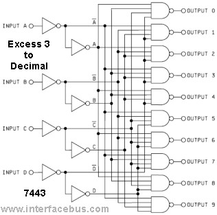
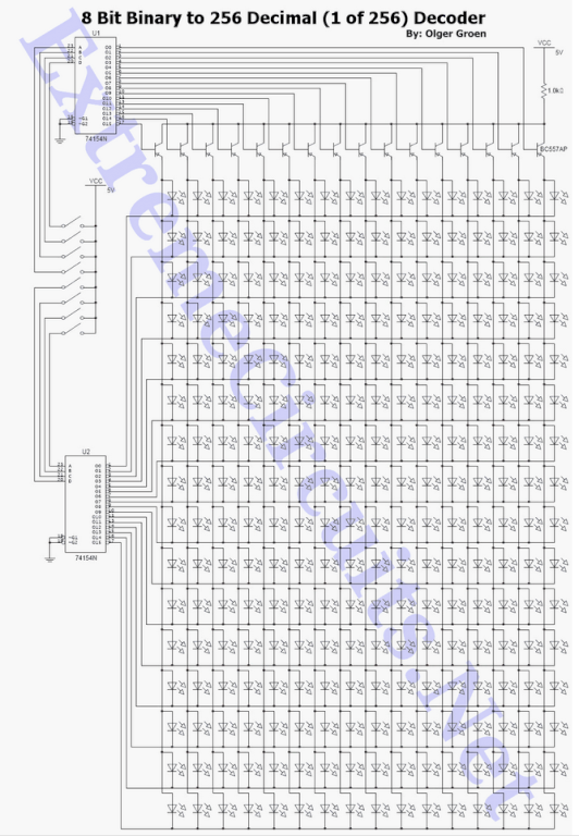
8 Bit Binary to 256 Decimal (1 of 256) Decoder
This is a guest post by Olger Groen. If you would like to write for ExtremeCircuits, please contact us through the contact form or leave a comment.
The provided description indicates an invitation for contributions to a platform focused on electronics. However, it lacks specific details regarding electronic schematics or circuit designs.
To create a comprehensive electronic schematic description, it is essential to focus on a particular circuit or electronic project. For instance, consider a simple LED blinking circuit using a 555 timer IC.
The circuit consists of a 555 timer configured in astable mode, where it generates a square wave output that alternates the state of the LED. The components required for this circuit include a 555 timer IC, two resistors (R1 and R2), a capacitor (C1), and an LED with a suitable current-limiting resistor (R_LED).
The 555 timer's pins are connected as follows: Pin 1 (GND) to ground, Pin 2 (TRIG) to the junction of R1 and R2, Pin 3 (OUT) to the anode of the LED (through R_LED), Pin 4 (RESET) connected to VCC to disable the reset function, Pin 5 (CTRL) connected to ground via a capacitor for stability, Pin 6 (THRESH) connected to Pin 2, and Pin 7 (DISCH) connected to the junction of R1 and C1. Finally, Pin 8 (VCC) connects to the positive supply voltage.
The timing of the LED blinking is determined by the values of R1, R2, and C1. The duty cycle and frequency of the blinking can be adjusted by changing these component values. This simple yet effective circuit serves as a fundamental example of using a 555 timer in practical applications, illustrating basic principles of timing circuits and LED control.This is a guest post by Olger Groen . If you would like to write for ExtremeCircuits, then drop us an email via contact form or simply comment. A long tim.. 🔗 External reference
