
IC Excess-3 to Decimal Encoder Chip

The 5443 and 5444 ICs are part of the 74xx series, which is a family of digital logic integrated circuits. The 5443 is designed to perform Excess-3 decoding, a binary-coded decimal (BCD) representation that allows for easy arithmetic operations. The Excess-3 code is a non-weighted code used to express decimal numbers, where each decimal digit is represented by its equivalent binary value plus three. The 5444, while serving a similar purpose, may have different internal logic configurations that affect its decoding capabilities.
Both ICs utilize a standard 16-pin dual in-line package (DIP) configuration, which facilitates easy integration into various electronic designs. The pin configuration typically includes power supply pins, ground pins, and input/output pins that correspond to the function of the IC. The identical pin-out allows for straightforward replacement of one IC with another in a circuit, provided that the specific application does not require the unique internal functionality of each.
The functional schematic illustrates how the inputs are processed and decoded into the corresponding outputs. The decoding logic is crucial for ensuring that the digital signals are interpreted correctly, especially in applications where precise numerical representation is necessary. The internal connections of the 5443 and 5444 differentiate their operational characteristics, influencing factors such as propagation delay, power consumption, and overall performance.
The 7400 series, which includes the 5443 and 5444, is foundational in digital electronics, with components that are widely used in various applications, from simple logic gates to complex arithmetic operations. As technology advances, newer families of ICs have emerged, but the legacy of the 7400 series continues to influence modern circuit design and implementation.Note that the function diagram for either the 5443 and 5444 are identical, assuming a 16-pin dual In-line package. The difference resided in the internal connections as shown in the functional schematic and how the inputs are decoded.
That is, the pin-out and block diagram is identical, but the internal connections show the difference. Editor note; It is doubtful that an IC that performs a Excess 3 decode function is still in active production. In addition; the orginal 7400 series of parts is the oldest of the 74xx family. 🔗 External reference
Related Circuits
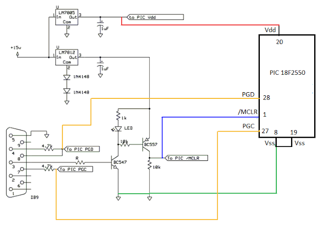
This is a simple COM port-based Microchip PIC microcontroller programmer, which is based on the JDM programmer. The entire programmer is constructed using commonly available components, allowing the programming of various microcontrollers using this schematic. To program a specific...
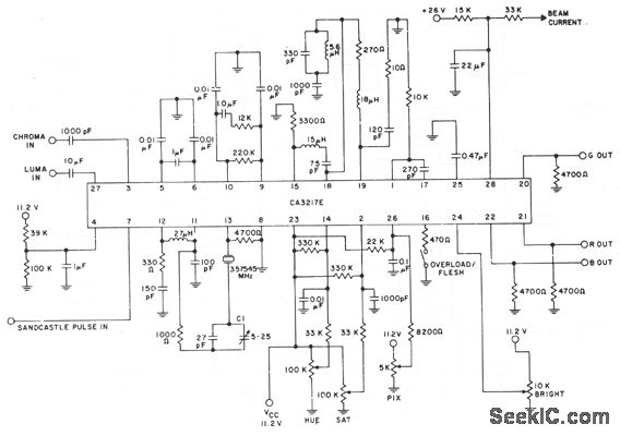
The CA3217E integrates all necessary circuit functions between the video detector and the RGB driver stages of a color television receiver. It decodes chroma signals to generate three distinct color signals, which are then combined with the luma to...
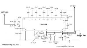
The following circuit illustrates a Single Chip FM Radio Circuit. This circuit is based on the IC TDA 7000 or TDA 7400. Features include a low-cost FM radio circuit. The Single Chip FM Radio Circuit utilizing the TDA 7000 or...
This page's mission is to assist in understanding the use of the STA013 MP3 decoder chip for designing an MP3 player. The player design outlined in subsequent pages utilizes the STA013, but this page aims to clarify the STA013...

An improved PL tone encoder has garnered significant interest since the previous article on a PL tone board. Due to this interest, enhancements have been made to the original PL tone design. Figure 1 illustrates an economical PL tone...
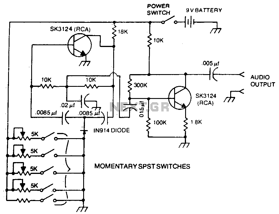
A basic twin-T circuit uses resistors to accurately set the frequency of the output tones, selected by pushbuttons. Momentary switches generate a tone only when the button is pressed. The twin-T oscillator circuit is a well-known electronic configuration used for...