
Amp Power Supply More Info
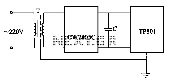
The operation of vacuum tube electronic circuits relies heavily on the conversion of AC voltage to DC voltage, which is crucial for the functionality of various electronic devices. The design of a DC power supply includes several essential components: the transformer, rectifier, filter, and voltage regulator. The transformer is responsible for adjusting the input voltage to the desired level, either stepping it up or down, depending on the requirements of the connected devices.
The rectifier, typically a diode or a bridge rectifier configuration, converts the alternating current (AC) to direct current (DC) by allowing current to flow in one direction only. This process results in pulsating DC, which still contains ripples. The filter circuit, often composed of capacitors and inductors, smooths out these ripples to produce a more stable DC output.
The voltage regulator is a critical component that ensures the output voltage remains consistent despite variations in load current. This is achieved through feedback mechanisms that adjust the output in real-time, maintaining the desired voltage level. Advanced regulators may also incorporate safety features, such as thermal shutdown and current limiting, to prevent damage under fault conditions.
In laboratory environments, bench power supplies are designed with user accessibility in mind, featuring binding posts for easy connection to experimental circuits. The inclusion of monitoring instruments like voltmeters and ammeters allows users to observe real-time measurements of voltage and current, facilitating better control and understanding of the experiments being conducted.
Protection mechanisms, including fuses, are integral to the safety and reliability of power supplies. The selection of appropriate fuse ratings and types is essential to prevent damage from overcurrent situations. Fast-acting fuses are suited for circuits with minimal inrush current, while time-delay fuses are better for applications where brief surges are expected, such as when large capacitors charge.
Overall, understanding the components and operation of a DC power supply is fundamental for designing and troubleshooting electronic circuits, particularly those utilizing vacuum tubes or requiring stable DC voltages for optimal performance.Vacuum tube electronic circuits operate from comparatively high DC voltages (150 to 600 volts). The Electric Utility supplies 120 volts AC. We have studied transformers and, therefore, we know that the 120 vAC line voltage could be stepped up to the necessary range but it would still be AC. The internal circuits of any device you can think of from a stereo receiver to an oscilloscope will not operate on AC. These devices must have internal circuits which change the AC to DC. Such a circuit is called a "DC power supply" or more often just "power supply". Figure 3. 1 shows the block diagram of a modern low-voltage regulated DC power supply. Each block has a specific purpose and will be dealt with in individual sections of this chapter. There is no difference in theory between a low voltage supply for transistors and a high voltage supply for tubes. Most audio amplifiers don`t have a voltage regulator but a section on additional filtering has taken the place of the regulator section both in this book and in the power supply.
The power supply is connected to the 120 vAC power line by a plug. Many power supplies (those used in laboratory equipment) have a plug with a third wire which connects the metal chassis of the instrument to earth ground. The fuse and switch constitute the protection circuits. The fuse helps to protect the power supply against circuit component failures and mistaken connections.
The switch permits the power supply to be turned on and off. The transformer steps the 120 volts of the AC line down or up as required by the devices being powered. The rectifier changes the AC from the transformer to pulsating DC. The filter reduces the magnitude of the pulsations and smoothes out the DC. The regulator reduces the pulsations to a very small value and also holds the output voltage constant regardless of the load current.
The regulator also contains circuits which will shut down the power supply if the load current becomes too large or the temperature of the regulator becomes too high. If the power supply is part of something else, such as an oscilloscope, an FM tuner, or an amplifier the output of the power supply is delivered to the internal circuits of the instrument and is not available to the operator.
If the power supply is a laboratory bench power supply, its output is connected to binding posts on the supply`s front panel for the purpose of powering experimental circuits. A laboratory bench power supply may also include a voltmeter and an ammeter to permit the operator to monitor the voltage and current which are supplied to the load.
All power supplies require protection from overloads and internal circuit faults. The most obvious protection device is a fuse. The type of fuse most commonly used in electronics equipment is a fine metal wire contained in a small glass tube with a metal cap on each end for electrical connection. The wire is made of a metal alloy with a low melting temperature, such as solder (40% led and 60% tin).
If excessive current flows through the fuse the thin metal wire will melt, opening the circuit and turning off the current. Fuses of the type described above are manufactured in current ratings from 1/200 ampere to 30 amperes.
Fuses are often placed in the primary circuit of the transformer. If a transformer develops an internal fault it can catch fire if the power is not shut off by an open fuse. There should always be a fuse in the primary of a power transformer. Many low-cost "wall transformers" do not have fuses in their primary circuits. These units present a constant fire hazard to any building in which they are used. There are two types of fuses, fast-acting and time delay. Time delay fuses are often called slow-blow fuses. Power supplies which have very large filter capacitors and semiconductor rectifiers will draw a very large current for a very short time after being turned on.
Have you ever noticed a flicker of t 🔗 External reference
Related Circuits
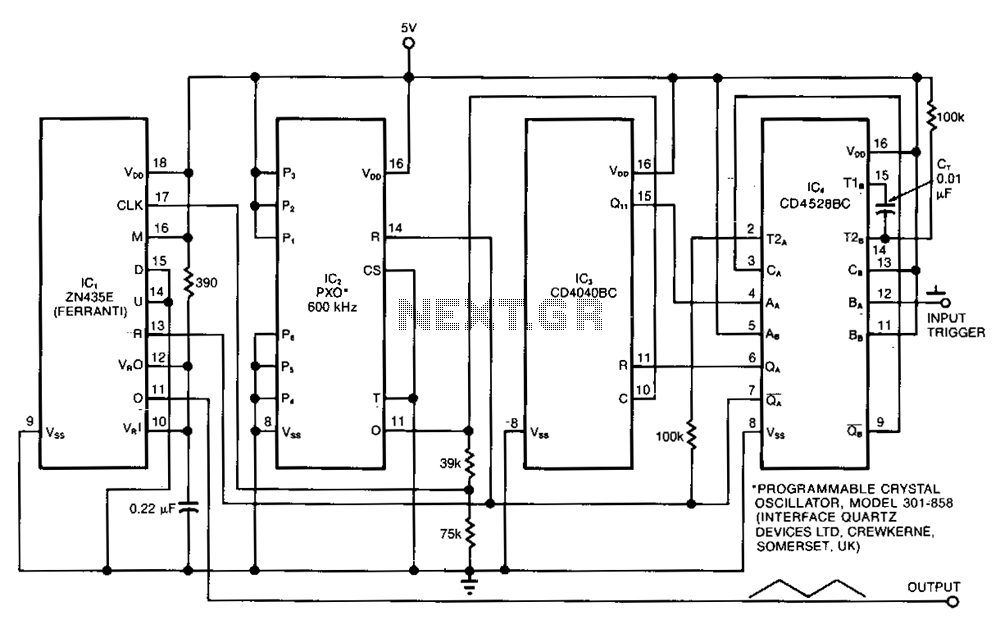
The ramp generator serves as a cost-effective alternative to commercial function generators, offering a more linear and repeatable output compared to traditional analog integrators. This circuit produces a triangle waveform in burst mode, generating two cycles of 10.24 ms...
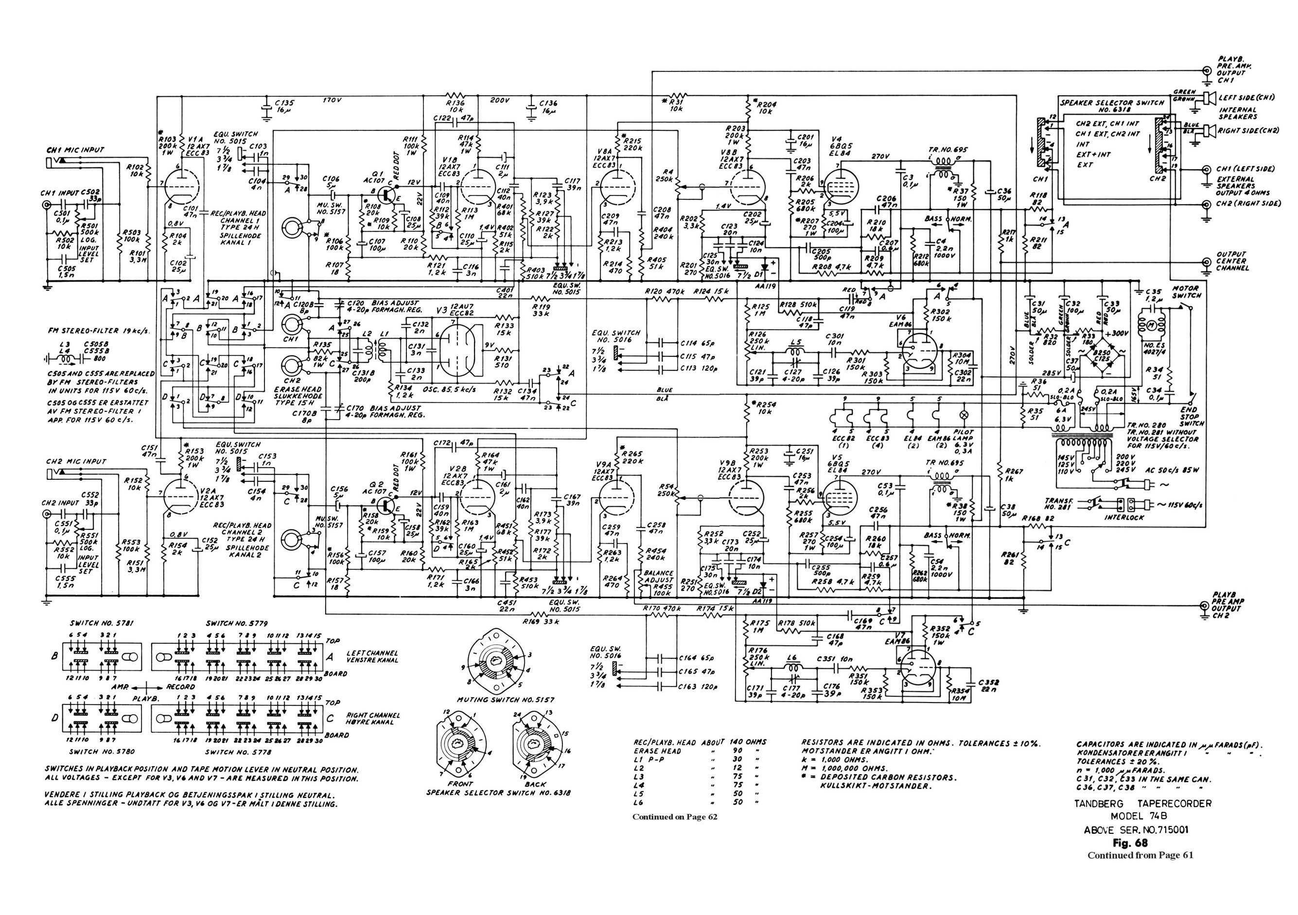
A Tandberg 74B has been acquired second-hand. The internal components are original, with the exception of previously replaced tubes. The Tandberg 74B is a high-fidelity stereo amplifier known for its robust build quality and excellent sound reproduction. This model...
High-precision voltage regulator, isolation transformer with the correct wiring, and low-pass filter to enhance the electrical noise immunity of the source portion. The wiring in Figures 20-48 and 20-49 is illustrated in the figures. Chokes (L1, L2) should have...
This circuit is very simple, consisting of fewer than 12 components, designed to build a DC to AC converter. The principle of this circuit involves generating a 50/60Hz frequency using the IC CD4047. The output from pins 10 and...
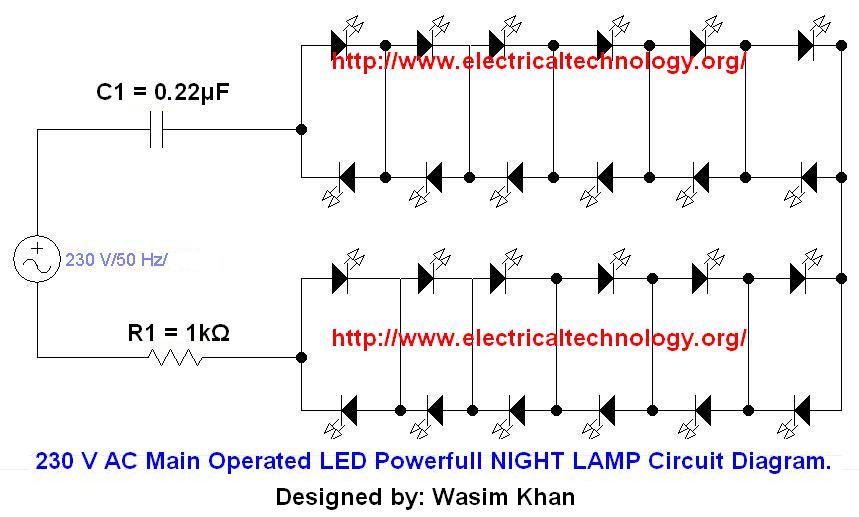
If you plan to use this circuit with a 110V 60Hz supply instead of a 230V 50Hz supply, or if you intend to modify this circuit, please refer to the section titled "Common Questions about this Circuit" found below...
The computer needs at least 180 millivolts peak-to-peak and the condenser microphone in my headset produces about 20 millivolts peak-to-peak into a 2.2k load with normal speech levels. There are USB ports on the machines, so I can use...